










Propagation delay is what forces FR4 PCB length matching. Once rise times drop below a nanosecond, the physical difference between two traces stops being abstract and starts eating into setup and hold margins. On FR4 the velocity is slow enough that a few hundred mils of mismatch already equals tens of picoseconds. That is enough to break many interfaces.
Most designers still treat length matching as a checkbox. The real question is whether the skew budget of the interface actually requires it, and how tight the tolerance must be before the matching itself creates new problems.
How Propagation Delay on FR4 Sets the Matching Requirement
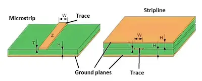
FR4 dielectric constant sits around 4.2-4.5 at 1 GHz. Effective Er for a microstrip is lower, typically 3.3-3.6. That gives a propagation delay of roughly 140-160 ps per inch on outer layers. Stripline, fully surrounded by FR4, lands closer to 170-180 ps per inch.
A 200 mil length difference therefore produces 28-36 ps of skew on microstrip and nearly 36 ps on stripline. At DDR4 rates or PCIe Gen3/4 edge rates, 30-40 ps is a meaningful fraction of the available timing window. Below a few hundred megahertz the same difference is usually invisible. The material itself does not change; the timing budget does.
When PCB Trace Length Matching Is Actually Required
Not every net needs matching. Length matching only matters when the interface timing budget is tighter than the uncontrolled routing skew that the layout will produce.
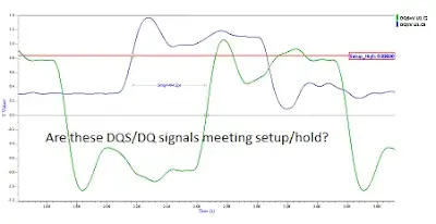
Source-synchronous parallel buses are the classic case. Data lines must stay inside a defined window relative to the strobe or clock. DDR memory is the clearest example: DQ/DQS matching is mandatory; address and command groups are matched relative to the clock with a looser budget. Parallel ADCs or DACs with simultaneous sampling have the same constraint.
Differential serial interfaces need intra-pair matching first. PCIe, USB 3.x, SATA, HDMI, and DisplayPort all require the positive and negative legs of each pair to be within a few mils. Lane-to-lane matching is secondary and often looser, limited by the receiver's deskew capability.
Clock distribution trees matter when multiple loads must see the same edge within a few tens of picoseconds. Everything else-low-speed GPIO, I2C, SPI under 50 MHz-rarely justifies the extra routing effort.
Interface-Specific Matching Rules and Realistic Tolerances
Tolerances should come from the timing analysis, not from habit. Still, certain numbers appear repeatedly in production designs because they sit inside the typical silicon budget.
PCIe Gen3/4 intra-pair matching is commonly held to ±5 mils or tighter. The differential pair itself is short and the receiver deskew window is limited. Lane-to-lane matching can often open to ±20-50 mils depending on the root complex.
DDR3/4 DQ-to-DQS matching is usually specified in the memory controller datasheet as a total skew budget that already includes package and on-die delay. On the PCB that frequently translates to ±10 mils or ±15 mils once the package length is subtracted. Address/command groups are typically allowed ±50 mils or more relative to the clock.
HDMI and DisplayPort follow similar intra-pair rules to PCIe. USB 3.x SuperSpeed pairs are also in the ±5 mil range. For older parallel buses such as LVDS camera interfaces, ±20 mils is often sufficient.
Setting the tolerance tighter than the timing analysis requires is pure cost. Extra serpentine length increases insertion loss and the chance of impedance discontinuities. Setting it looser than the silicon can tolerate simply fails timing at temperature or voltage corners.
Designing Serpentine Traces That Do Not Create New Problems
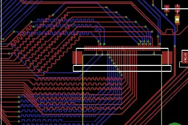
Serpentine (meander) routing is the usual way to equalize length. Done poorly it adds crosstalk, impedance dips, and unnecessary delay.
Keep the spacing between parallel segments of the meander at least three times the trace width. Closer spacing turns the serpentine into a distributed coupled line; the effective delay becomes longer than the geometric length and the impedance drops. Use 45-degree or curved bends rather than 90-degree corners. Sharp corners radiate and create small inductive discontinuities that accumulate at multi-gigabit rates.
Place the meanders on the longer nets, not the shorter ones. Adding length to a short net is usually cleaner than trying to shorten a long net by aggressive via juggling. Keep the serpentine away from other high-speed pairs; the parallel segments act as aggressors.
Calculate electrical length, not just center-line geometry. Most layout tools report the routed length correctly, but corners and neck-downs still need a quick manual check if the tolerance is under 5 mils. On FR4 the difference between geometric and electrical length is small for well-designed serpentines, but it is not zero.
Manufacturing Realities That Affect Matched Lengths
Etch tolerance on outer layers is typically ±0.5 mil to ±1 mil per side. That changes the physical length of a long serpentine by only a few mils even on a dense meander. Inner-layer etch is more controlled. The larger variable is usually the designer's own via transitions and layer changes; each via adds a fixed delay that must be included in the matching budget.
CAM engineers do not adjust matched groups unless the designer explicitly requests it. Once the lengths are locked in the design database, the fab will reproduce them within the etch and registration tolerances of the process. If the matching is already marginal, those few mils of process variation can push the design outside the timing window.
The practical rule is simple: leave enough margin in the length-matching tolerance so that normal fabrication variation does not consume the entire budget. A ±5 mil target with ±2 mil process uncertainty is already tight; a ±10 mil target leaves room.
Engineering Judgment on FR4 Length Matching
FR4 PCB length matching is required only when the interface timing budget is smaller than the uncontrolled routing skew the layout will produce. Propagation delay on FR4 makes a few hundred mils of mismatch equal to tens of picoseconds-enough to matter at multi-gigabit rates and for tight parallel buses.
Set the tolerance from the timing analysis after subtracting package and on-die delays. Apply the tightest numbers only to intra-pair differential matching; open the tolerance for inter-pair and group matching whenever the silicon allows it. Design the serpentine so that spacing, bend style, and placement do not introduce coupling or impedance steps that erase the benefit of the matching.
Matching is not free. Extra length adds loss and routing congestion. Use it only where the timing actually demands it, and keep the geometry clean enough that the matched nets still look like controlled-impedance transmission lines after fabrication.






