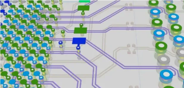
Why a small resistor appears on some PCB signal lines
If you design PCBs, you have probably seen a small resistor placed in series on some signal traces. That inconspicuous component helps control the signal and prevent it from "misbehaving." Technically, it provides damping and assists impedance matching to reduce signal reflections.
For example, data lines between a CPU and DDR memory often include a series resistor on each line. The resistor helps the signal behave and reduces reflections that cause overshoot and ringing.
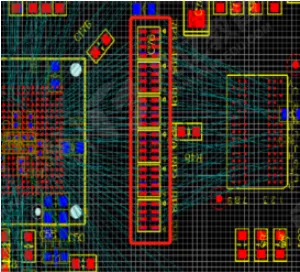
Simulation: build a simple model
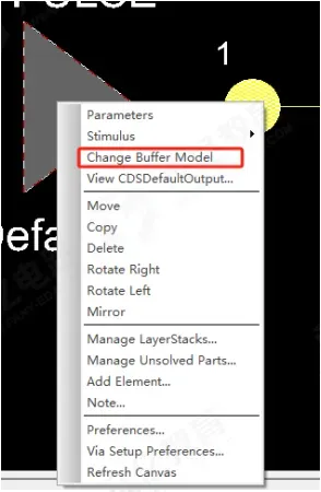
To make the effect clear, a simulation was set up. The transmission line impedance was set to 50 ohm, and the transmitter (TX) and receiver (RX) were modeled as 1.8 V high-speed drivers and receivers to mimic a realistic signal path.
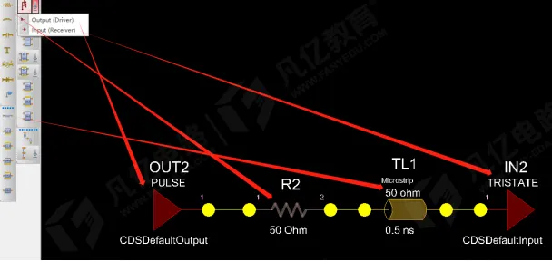
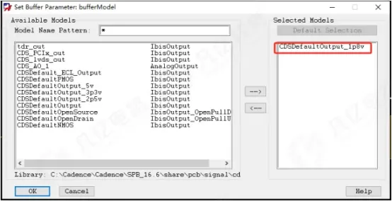
Different resistor values produce different effects
Six resistor values were tested: 0 ohm, 10 ohm, 20 ohm, 30 ohm, 40 ohm, and 50 ohm, to observe their impact on signal reflections.
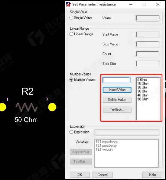
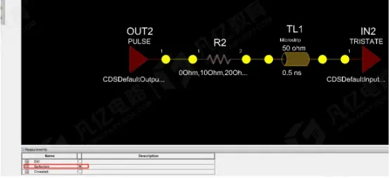
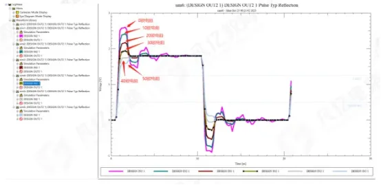
The simulation results show clear differences:
- 0 ohm (no series resistor): the signal drives too hard and exhibits severe overshoot.
- 10 ohm and 20 ohm: overshoot is progressively reduced and the waveform looks cleaner.
- 30 ohm: the waveform is the most stable, with minimal overshoot and good edge behavior.
- 40 ohm and 50 ohm: the signal rise becomes slower and undershoot appears, which is undesirable.
How to choose the series resistor
The series resistor should neither be as small as possible nor as large as possible. The key is for the sum of the transmitter's source resistance and the series resistor to equal or approximate the transmission line impedance (for example, 50 ohm) to suppress reflections.
In practice, designers often start with 22-30 ohm. The exact value should be validated with simulation, or adjusted during board bring-up and tuning until the signal meets the required margins.
Note: Why modern DDR sometimes lacks external series resistors
Many modern DDR designs use on-die termination (ODT), which integrates termination resistors inside the memory or controller and allows them to be adjusted. ODT typically applies to data lines; address, control, and clock lines may still require external termination or series resistors to avoid reflections.
Also, place any series resistor as close to the transmitter (driver) as possible. If it is placed too far from the source, it will not effectively improve the signal.