An audio interface provides connectivity between microphones and other audio sources and a host system, bridging analog and digital domains. Typical interfaces include Audio In and Audio Out, along with digital audio buses such as I2S, PDM, and SPDIF. Because audio signals span low-frequency analog paths and moderate-speed digital clocks, PCB design must balance noise immunity, crosstalk control, power integrity, and electrostatic discharge (ESD) robustness.
General PCB Routing Requirements
-
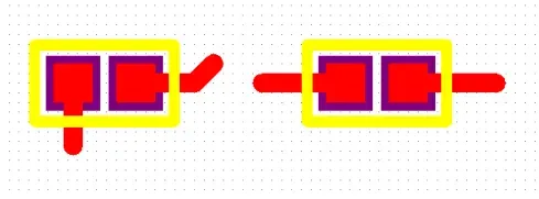
Series damping for clocks: Place a 22 Ω series resistor on every clock signal and locate it as close as possible to the RK3588 device. This helps improve signal quality by damping high-frequency components and suppressing reflections.
-
Clock isolation and ground guarding: Do not route clock signals adjacent to each other to avoid crosstalk. Provide continuous ground guarding for the entire length of each clock trace. Insert a ground via within every 300 mil along the guard to maintain a low-impedance return path. See Figure 1.
-
Decoupling placement: Place decoupling capacitors for each IO power rail as close as possible to the corresponding IC pins to minimize loop inductance and stabilize the supply. See Figure 2.
-
Connector placement: Place audio connectors according to mechanical constraints. If there are no structural limitations, locate them at the board edge to facilitate insertion and removal.
-
IC proximity: Place the audio-related ICs close to their connectors. Keep analog audio signal paths as short as possible.
-
Audio In/Out routing: Controlled impedance is not required for baseband audio In/Out. Widen traces to 15 mil and provide full ground guarding along the route. Insert ground vias at intervals no greater than 300 mil to tie the guard to the ground plane.
-
ESD protection at the connector: Place ESD protection devices as close as possible to the audio connector. Ensure the signal path passes through the ESD device before entering the connector. Avoid changing layers with vias in this segment. See Figure 3.
-
Keepout from noisy areas: Keep audio signals away from inductors, RF signals, and RF components.
-
I2S and PDM clock topology: When one I2S interface drives multiple devices, route the related clock in a daisy-chain topology to minimize stubs. Similarly, for a PDM interface serving multiple devices, route the related clock in a daisy chain. If GPIO resources allow, both clocks in a PDM group can be used to optimize branch routing.
-
Separation from high-speed buses: Keep all audio signals away from high-speed signals such as LCD and DRAM. Do not route audio signals on a layer adjacent to high-speed signal layers; the adjacent layer for audio should be a continuous ground plane. Avoid via transitions near high-speed lines to prevent coupling and noise injection.
-
SPDIF shielding: Provide full ground guarding for SPDIF signals, with ground vias at spacing no greater than 300 mil, to control emissions and susceptibility along the route.
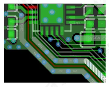
Figure 1 | Ground guarding and via stitching for clock traces
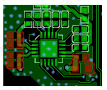
Figure 2 | Placement of decoupling capacitors
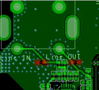
Figure 3 | Placement of ESD protection devices near the audio connector
Device-Specific Audio Signal Guidelines
Unless a device vendor’s design guide specifies otherwise, follow these practices for common audio peripherals:
-
Speaker outputs (SPKP/SPKN): Route the differential speaker outputs as a coupled pair and ground-guard the entire pair. Set the trace width based on the peak output current to control IR drop and temperature rise. Keep routes as short as practical to limit series resistance.
-
Output filtering: If ferrite beads or LC filters are used at the amplifier output, place them close to the amplifier pins to minimize loop area and improve EMI performance.
-
Headphone left/right channels: Provide separate ground guarding for left and right channels to reduce crosstalk and improve isolation. Use a trace width greater than 10 mil.
-
Microphone routing: For single-ended microphones, route MIC signals individually and provide ground guarding for each. For differential microphones—including pseudo-differential implementations—route as differential pairs and ground-guard the entire pair.
-
Microphone trace width: Use a trace width of at least 8 mil for MIC signals.
-
TVS protection for jacks and microphones: Place TVS diodes as close as possible to the connector. The recommended topology is: headphone jack/microphone → TVS → IC. This ensures that during an ESD event, the current is shunted by the TVS before reaching the IC. Avoid stubs on the TVS-connected traces. For the TVS ground pin, increase ground via count to improve discharge capability; provide at least two vias of 0.4 mm × 0.2 mm to the ground plane.
Engineering Rationale and Implementation Notes
Why clocks need series resistors and isolation
Digital audio clocks such as I2S MCLK, BCLK, or PDM CLK have fast edges that can excite reflections and ringing if the source, line, and load impedances are not well matched. A small series resistor near the driver acts as a source termination, reducing overshoot/undershoot and improving waveform fidelity. Keeping clock lines separated and individually ground-guarded limits capacitive and inductive coupling between parallel clock routes, which otherwise increases jitter and degrades timing margins at the receiver.
Ground guarding and via stitching for audio and clock traces
"Ground guarding" refers to flanking a sensitive or noisy trace with grounded copper and stitching that copper to the ground plane at regular intervals with vias. This technique provides a well-defined return path immediately adjacent to the signal path and reduces both radiated and coupled noise. The specified ground via spacing (no greater than 300 mil) helps maintain a continuous low-impedance return, especially across layer transitions and board regions where solid ground may be interrupted by splits or voids.
Decoupling close to IO rails
Audio codecs, amplifiers, and SoC IO rails benefit from local decoupling to suppress supply noise and keep transient currents local. Short connections to decoupling capacitors reduce loop inductance, lowering the impedance seen by fast transient currents and preventing supply fluctuations that can manifest as audible artifacts or digital timing instability.
Why baseband audio typically does not require controlled impedance
Audio In/Out baseband signals occupy comparatively low frequencies and long wavelengths, so their signal integrity is primarily limited by resistance, ground noise, and coupling rather than characteristic impedance control. As a result, widening traces (for lower resistance and better current handling) and applying ground guarding deliver more benefit than tight impedance control. The 15 mil width recommendation is a practical baseline; increase width when drive current or length warrants.
Connector placement and short analog paths
Locating audio connectors at the board edge simplifies mechanical integration and reduces stress on the board. Placing the audio ICs near their respective connectors minimizes the length of analog runs and reduces opportunities for noise coupling. Shorter runs also make it easier to ground-guard effectively, and they limit trace resistance in speaker or headphone outputs where load currents are higher.
ESD protection at the entry point
Audio jacks are user-accessible and subject to ESD events. Positioning the TVS/ESD component right at the connector ensures the surge current is diverted to ground before it can propagate into the board. Keep the path from the connector pin to the TVS and from the TVS to ground as short and straight as possible. Using multiple ground vias on the TVS ground pin reduces inductance in the discharge path and increases the protection effectiveness. Avoid via transitions or layer changes in the short segment between the connector and TVS to prevent introducing inductive discontinuities.
Maintaining distance from inductors, RF, and high-speed buses
Inductors in power circuits can radiate switching noise that readily couples into high-impedance audio paths. RF circuits can inject or receive unwanted energy if audio lines run nearby. Likewise, LCD, DRAM, and other high-speed digital buses can couple transient fields into adjacent audio layers. Route audio on layers adjacent to a continuous ground plane, keep sufficient physical spacing from inductors and RF areas, and avoid via transitions near high-speed signals. This reduces both susceptibility and emissions.
Daisy-chain clocking for multi-drop I2S and PDM
When a single I2S or PDM master drives clocks to multiple slaves, a daisy-chain topology minimizes stubs and discontinuities. Each device taps the clock along the route rather than through a T-branch, which would create impedance discontinuities and reflections. If the platform provides two available clocks in a PDM group and GPIO resources are sufficient, using both clocks can reduce branching and simplify routing while maintaining signal quality.
SPDIF considerations
SPDIF is a digital audio interface that can run at moderate edge rates. Ground guarding with regular via stitching along the SPDIF trace helps contain fields, control interference with nearby circuits, and maintain a stable return path. Ensure a continuous ground reference under the SPDIF route and avoid running it near sensitive analog audio paths.
Headphone, speaker, and microphone layout nuances
Headphone channels benefit from separate ground guards to improve isolation, as shared ground paths can inject channel-to-channel noise. For speaker outputs, treat SPKP/SPKN as a current-carrying differential pair. Sizing the width for the expected peak current reduces voltage drop and heat. For microphones, single-ended routes should be individually guarded, while differential or pseudo-differential microphones should be routed as pairs with consistent spacing and guarded as a group to reject common-mode interference.
By combining disciplined routing, robust ground referencing, proper decoupling, and careful ESD protection placement, audio interface circuits can achieve low noise, good immunity, and reliable operation across a wide range of system environments.