In PCB layout, there are times when a copper edge, trace segment, or board outline must be shifted by an exact distance while maintaining its angle. Moving horizontal or vertical segments is straightforward because the displacement aligns with the X and Y axes. The challenge arises when the feature is diagonal, for example at 45°, and you need a precise 1 mm parallel shift. This article presents a practical workflow using standard EDA features—snapping, reference vias, and rotation—to achieve an exact diagonal displacement without guesswork. The method is robust, works with most PCB editors, and is particularly convenient for 45° segments that frequently appear in routing and board outlines.
The technique uses a helper via for alignment and a simple 45° rotation trick to translate a precise axis-aligned move into an equally precise diagonal move. While many editors provide direct "move by distance and angle" commands or parallel-offset features, this workflow is universally applicable, especially when such functions are not available or are awkward to use.
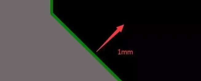
Figure 1 | Example layout with a diagonal feature that needs a controlled offset
Problem Definition: What Does "Move a Diagonal by 1 mm" Mean?
"Move by 1 mm" can be interpreted in several ways. In most PCB workflows, it means translating a feature parallel to itself by 1 mm—i.e., shifting along the feature's normal direction so that the geometry remains parallel and its angle is preserved. For a 45° trace segment or board edge, you want the entire segment to move 1 mm in the direction perpendicular to its length, not merely 1 mm in X or Y.
If your tool accepts polar moves (distance plus angle), the command is straightforward: move by 1.000 mm at an angle normal to the edge. However, when the tool only allows axis-aligned delta entries or snapping, the following method converts an exact horizontal move into the desired diagonal move using rotation and snapping.
Rotation-and-Snap Workflow for Precise Diagonal Displacement
This method uses a via (or any round reference pad) as a precise pick-up and drop reference. The core idea is to perform an exact axis-aligned move and then map that move into a diagonal offset via a 45° rotation, leveraging snap-to-center behavior.
- Place a reference via at a known control point:
- Pick a point on the diagonal feature that you can reliably snap to—for instance, a trace endpoint, a vertex of the board edge, or a construction feature. Place a via at this point to serve as a stable reference. Ensure snap-to-center is enabled.
- Apply a precise axis-aligned move:
- Perform a controlled horizontal move of the via by the exact increment you want to translate diagonally. For example, move it by 0.10 mm if you plan to build the displacement in 0.10 mm steps, or directly by 1.00 mm if you will perform the full shift in one operation.
- Create a rotated helper:
- Copy the reference via and rotate the copy by 45°. This establishes a helper reference aligned with the 45° direction. For 45° diagonals, the rotation aligns the axis with the diagonal so that an axis-aligned displacement translates directly into a diagonal move when you snap back onto the rotated helper.
- Snap the feature to the rotated reference:
- Use the editor's grab/snap behavior to place the diagonal feature onto the rotated helper via center. Because snap is exact, the resulting move equals the original axis-aligned displacement but mapped along the diagonal direction.
- Repeat if needed:
- If you used 0.10 mm steps for fine control, repeating the move ten times gives an exact 1.00 mm diagonal displacement. Alternatively, if you moved 1.00 mm in the axis-aligned step, a single operation completes the 1 mm diagonal shift.
This approach takes advantage of the fact that a 45° rotation converts a horizontal displacement into an equivalent displacement along the 45° direction. By snapping to the rotated helper, the editor applies the transformed move precisely, avoiding manual calculation of vector components.
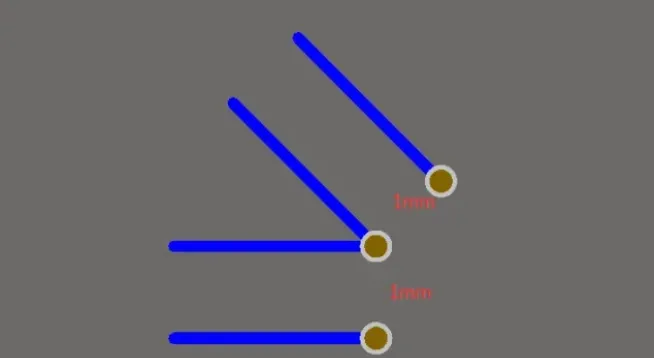
Figure 2 | Using a rotated helper via and snap-to-center to realize an exact diagonal move
Why the 45° Trick Works
Moving a feature by a distance d along a direction with angle θ relative to the X axis is a vector operation. The displacement's Cartesian components are:
- dx = d × cos θ
- dy = d × sin θ
For a 45° diagonal, cos 45° = sin 45° = 1/√2, so the X and Y components of a 1.000 mm move are both approximately 0.7071 mm. One way to achieve the shift is to enter dx = 0.7071 mm and dy = 0.7071 mm simultaneously—if your editor supports a two-axis delta entry.
The rotation-and-snap method avoids component math and round-off concerns. By rotating the reference by 45°, an axis-aligned move of length d becomes aligned with the diagonal direction. Snapping the feature to the rotated helper applies the exact move along the diagonal without manually computing dx and dy. This is particularly convenient when your editor provides precise snapping but a limited move-by-angle interface.
Practical Tips for Consistency and Accuracy
- Grid and units:
- Set the grid to a resolution that divides cleanly into your target displacement. For example, use a 0.10 mm grid if you plan to build 1.00 mm by ten incremental steps. Make sure the editor units are set to mm to avoid conversion errors.
- Snapping:
- Enable snap-to-center for vias and pads. Disable or reduce conflicting snaps (e.g., to arbitrary polygon vertices) that might cause unintended placement.
- Relative origin:
- If your editor supports a temporary or relative origin, place it at the starting control point. Some tools show live delta coordinates, which helps confirm each increment.
- Helper isolation:
- Place helpers (vias or construction pads) on a mechanical or helper layer to prevent DRC conflicts. Delete or hide them after the operation to keep the design clean.
- One-step vs incremental moves:
- Incremental 0.10 mm steps provide fine control and a chance to visually verify each move. If you are confident in your setup, a single 1.00 mm axis-aligned move followed by the rotation snap accomplishes the task more quickly.
- Angle generalization:
- The method generalizes beyond 45°. Replace 45° with the feature's angle θ. Rotate your helper by θ, apply an axis move of d, and snap. The same logic applies because rotation maps the axis-aligned displacement into the desired direction.
Alternative CAD Workflows
Depending on your editor, you may have other options to accomplish an exact 1 mm diagonal displacement:
- Move by distance and angle:
- Some tools accept polar entries such as "distance = 1.000, angle = 45°." This directly shifts the feature by the specified vector.
- Parallel copy/offset:
- For board outlines and mechanical shapes, a parallel offset command can create a replica offset by exactly 1.000 mm. For traces, a parallel copy or track offset function may be available.
- Constraint/dimension-based edits:
- If your editor supports parametric constraints, you can dimension the offset and let the constraint solver maintain exact spacing as you edit the geometry.
- Dual-axis delta entry:
- Enter dx and dy directly using dx = d × cos θ and dy = d × sin θ. For a 1 mm shift at 45°, use 0.7071 mm in both axes.
The rotation-and-snap technique remains valuable when the editor's polar move or parallel offset functions are unavailable, imprecise, or cumbersome for a specific object type.
Use Cases in PCB Design
- Clearance tuning around angled edges:
- Maintain consistent clearance between a diagonal copper edge and a keep-out, slot, or mechanical boundary by shifting the edge precisely.
- Fine adjustment of 45° trace segments:
- Push a 45° segment outward by exactly 1 mm to meet spacing rules or align with a via fence without breaking the segment's angle.
- Board outline refinement:
- Apply controlled offsets to beveled corners or chamfers to meet enclosure tolerances or assembly clearances.
- High-voltage creepage/clearance management:
- When creepage or clearance must be maintained along a slanted boundary, a precise diagonal shift helps preserve required distances without altering the feature's orientation.
- High-speed spacing consistency:
- Uniform spacing along diagonal routes can help manage coupling and impedance environments, especially in dense areas where 45° segments are used to maintain smooth transitions.
Common Pitfalls and How to Avoid Them
- Misinterpreting the displacement:
- Ensure that "1 mm" refers to a parallel shift of the feature, not a screen-projected or axis-only move.
- Rounding errors:
- If combining multiple small steps (e.g., ten 0.10 mm moves), use a grid setting that prevents cumulative rounding. Confirm the final displacement with a measurement tool.
- Snapping to the wrong reference:
- Turn off unnecessary snaps and verify you are snapping to the helper via's center, not to a nearby polygon or silkscreen element.
- Forgetting helper cleanup:
- Remove or hide helper vias and construction geometry after the operation to keep the design tidy and avoid DRC noise.
Worked Example: 1 mm Along a 45° Segment
Suppose you need to shift a 45° trace segment by exactly 1.000 mm without changing its angle:
- Place a via at the trace endpoint as a grab reference. Enable snap-to-center.
- Move the via horizontally by exactly 1.000 mm using the editor's precise move command or delta entry.
- Copy the via and rotate the copy by 45° to align the helper with the diagonal direction.
- Grab the trace endpoint and snap it onto the center of the rotated via. The trace translates by exactly 1.000 mm along its diagonal alignment.
- Confirm the displacement using measurement tools. Remove helper geometry.
If your grid or workflow favors finer increments, replace step 2 with a 0.10 mm move and repeat the 0.10 mm sequence ten times, verifying each step as needed.
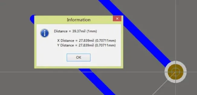
Figure 3 | Resulting geometry after an exact 1 mm parallel shift along a 45° feature
Conclusion
Shifting a diagonal feature by an exact value is a common but sometimes awkward task when an editor lacks a direct polar move or parallel-offset function for the object type. By leveraging a simple rotation-and-snap technique with a helper via, you can convert a precise axis-aligned displacement into an equally precise diagonal move. For 45° features, this method is especially quick and repeatable. Combined with careful control of grid, snapping, and measurement tools, it provides a dependable way to maintain exact spacing and geometric integrity across a wide range of PCB layout tasks.