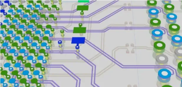
During PCB layout, it is often necessary to isolate and operate on all signal connections tied to a single component. Typical scenarios include replacing a device footprint, reworking a crowded area, rerouting differential pairs, or applying engineering change orders (ECOs). Efficiently selecting every related connection and then safely removing the routed copper for those connections can save significant time and prevent unintended edits elsewhere in the board. This article explains practical methods to select all connections associated with a component and to unroute those connections in a controlled manner, along with the engineering context and precautions to consider.
Selecting All Connections for a Component
To gather every connection associated with a device, many PCB editors offer command sequences and selection shortcuts that target a component's connectivity as a group.
Typical workflow:
- Use the hotkey S to enter or bring up the selection/filter context.
- Run Component Connections to select the physical connections associated with the device. This captures the routed copper objects—such as traces and vias—that are physically connected to the component's pins.
- Alternatively, run Component Nets to select the nets associated with the device. This targets the logical net objects tied to the component, which can then be used to select, highlight, or operate on all copper objects belonging to those nets.
The difference between Component Connections and Component Nets is subtle but important:
- Component Connections focuses on current physical connectivity. It selects the actual copper geometries that are presently attached to the device's pads, such as clines, arcs, and vias, regardless of whether the entire net is routed across the board. This is helpful when you want to manipulate or evaluate only the local routing attached to the component.
- Component Nets focuses on topology. It selects all nets that include the component's pins, even if the routing extends far across the board and includes multiple branches, layers, and other devices. This is useful when you want to apply operations or visual highlighting across the complete net paths, or when you want to isolate a set of nets for rule scoping, length tuning, or timing analysis.
In practice, both selection modes are valuable. For local edits—such as cleaning up escape routing from a BGA or restructuring fan-out—it is typically more efficient to select physical connections. For global edits—such as modifying constraints, highlighting for review, or bulk operations on a net group—selecting nets is more appropriate.
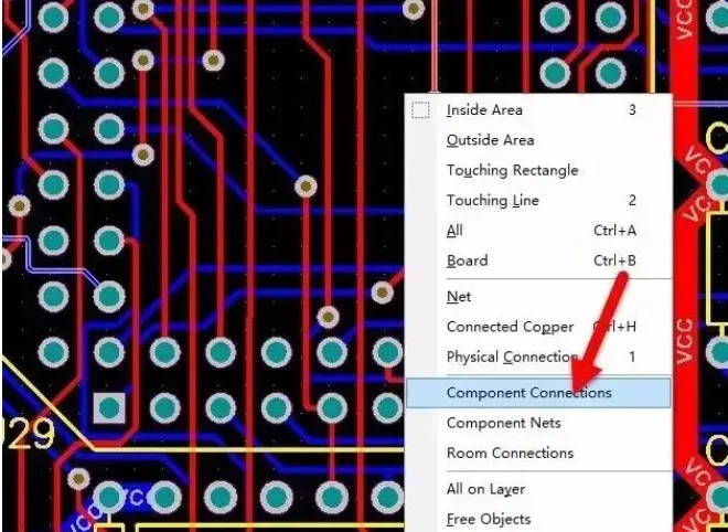
Figure 1 | Selecting a component's physical connections versus its associated nets targets different levels of connectivity.
Tips for Reliable Selection
- Use selection filters to restrict edits to traces, vias, and pads. Filtering prevents accidentally selecting mechanical shapes, text, or keepouts.
- Work layer-by-layer when needed. For dense designs, temporarily enabling only the relevant signal layers and the target component's layer can improve selection accuracy.
- Highlight instead of immediate selection. Many tools let you highlight nets first, providing visual confirmation before committing to a selection. This is useful for complex, branching nets.
- Cross-probe with the schematic. Verifying that the selected nets align with the schematic netlist ensures you are operating on the intended connectivity.
- Be mindful of differential pairs and net classes. If a component belongs to a differential pair or a specific net class, ensure both members or all class members are included when performing bulk operations.
Unrouting All Nets for a Component
When a device must be swapped, relocated, or rerouted from scratch, it is common to clear all existing copper associated with that component. A controlled way to do this is to unroute the component.
Menu path:
- Tools → Unroute Component
This operation removes the routed copper objects—traces and vias—connected to the selected component's pins. After unroute, the logical netlist remains intact, and airwires (rats) typically reappear, indicating that connectivity needs to be re-established. The schematic net definitions are not deleted; only the physical routing tied to that component is removed.
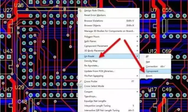
Figure 2 | Unrouting a component removes copper associated with its nets while preserving the netlist and airwires.
What Unroute Component Typically Affects
- Removes traces and arcs attached to the component's pins.
- Removes vias that are part of the local routing connected to those pins.
- Leaves logical net associations unchanged; airwires reappear to indicate unrouted connectivity.
- Does not alter the schematic or the net definitions.
Because the netlist remains intact, you can immediately reroute the affected nets. This is especially useful after a footprint change, pin swap, or a local re-layout of a congested region.
Engineering Considerations Before and After Unrouting
- Polygons and planes: If copper zones or planes connect to the affected nets, unroute may leave stubs or thermal connections until a repour is performed. After unroute, repour relevant shapes to update clearances and remove orphaned connections.
- Teardrops and post-processing: Any post-processing features like teardrops, fillets, or curved corners attached to the removed traces may also be cleared. Reapply such features after rerouting, if required by your process or DFM guidelines.
- Blind/buried and microvias: Ensure that via removal aligns with your stackup and via rules. If escape routing used microvias, double-check constraints and via stacks before rerouting.
- Keepouts and rooms: Confirm that local keepouts, component rooms, or placement fences still accommodate the intended new routing paths.
- Differential and length constraints: If the component participates in matched nets, differential pairs, or timing-constrained routes, retain or verify those constraints. After reroute, revalidate length matching, skew, and timing to restore SI compliance.
- DRC closure: After unroute and repour, run a design rule check to ensure no residual violations remain before starting new routing.
Understanding Component Connections vs. Nets
It helps to frame the distinction between physical connections and nets in graph terms:
- Nets are logical connectivity definitions derived from the schematic netlist. They describe which pins should be electrically connected but not how they are physically realized in copper.
- Connections in the layout are the physical realization of those nets—traces, arcs, and vias that form the actual copper paths between pins.
Because these two representations target different layers of abstraction, operations that act on “connections” usually change the copper immediately attached to the component, whereas operations acting on “nets” extend across the entire topology of the board. This is why both selection methods are provided and why choosing the right scope for the task at hand matters.
In particular:
- Use Component Connections when you need to manipulate, review, or delete only the copper immediately attached to a component's pads—such as clearing an escape, adjusting a fan-out, or reconstructing pin escapes after a package change.
- Use Component Nets when you need to select, highlight, or operate on the entire connectivity across the board—such as scoping constraints, isolating a net group for inspection, or preparing for global rerouting.
Practical Workflows and Safeguards
The following practices help ensure that selecting and unroute operations are controlled and reversible:
- Version control and backups: Commit a baseline before bulk edits or use a local save point. This allows easy rollback if unintended objects are removed.
- Locking critical items: Lock adjacent components or critical nets to prevent accidental movement or edits during selection and unroute operations in congested areas.
- Incremental repour: After unroute, perform a targeted repour of affected polygons to avoid global repours that may mask local issues or add noise to the DRC list.
- Scoped DRC: Run a localized or filtered DRC on the area or net group you modified. Clearing violations early avoids compounding problems in later routing phases.
- Cross-probing verification: Highlight the nets from both schematic and layout to ensure the intended nets were affected and that no unintended nets were touched.
- Constraint-preserving reroute: Ensure that net classes, differential pair definitions, and length rules are active before rerouting so new routes automatically adhere to design constraints.
Common Pitfalls and How to Avoid Them
- Residual copper or stubs: After unroute, small copper remnants can remain if they are not directly tied to the selected connections. Use copper cleanup tools or perform a focused repour to remove remnants.
- Orphaned vias: Vias not captured by the selection can remain disconnected. Enable via selection filters and visually inspect for orphans before rerouting.
- Unupdated shapes: Forgetting to repour copper after unroute can leave misleading connections on screen. Repour shapes to reflect the current connectivity state.
- Missing pair members: When working with differential pairs, ensure both members are selected and unrouted together to preserve timing and coupling relationships during reroute.
- Incorrect selection scope: Selecting nets when you intended to select only local connections—or vice versa—can lead to excessive edits. Review the scope in the status bar or selection dialog before executing destructive commands.
Summary
Efficient editing at the component level depends on choosing the right selection scope and using controlled unroute operations. Selecting Component Connections gives you precise control over the physical copper attached to a device, while selecting Component Nets lets you operate on the full logical connectivity across the board. The Tools → Unroute Component function removes only the routed copper for the selected device without altering the netlist, making it ideal for ECOs, footprint swaps, and focused rework. Combined with good selection habits, constraint-aware rerouting, and appropriate DRC checks, these workflows streamline complex layout edits while preserving design integrity.
SEO Title: Selecting and Unrouting Component-Related Nets in PCB Layout Meta Description: Learn how to select all connections or nets associated with a component and safely unroute them in PCB layout, including practical workflows, differences between connections and nets, and engineering precautions.