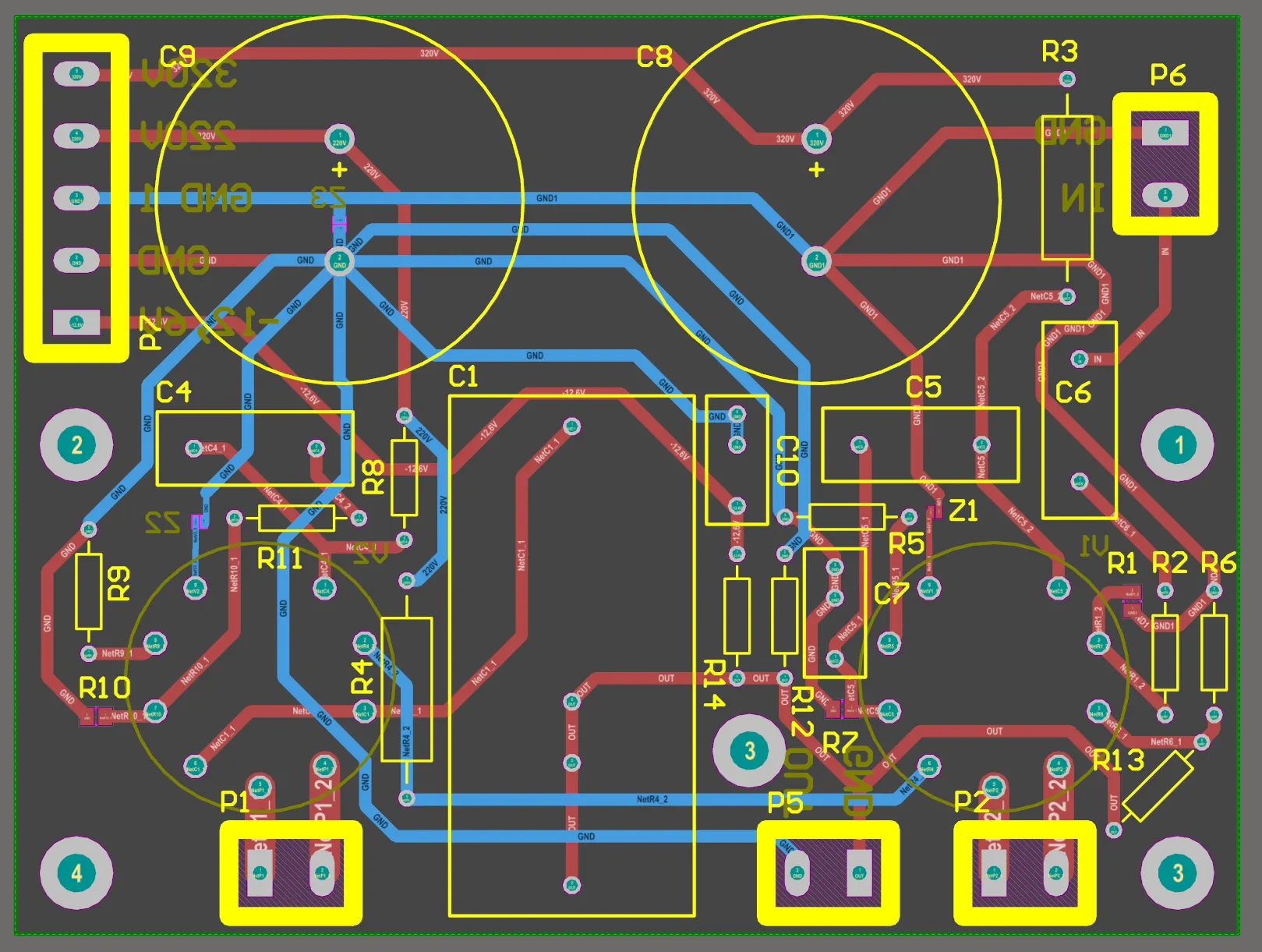
On many PCB designs a resistor sits in series on a signal net. That small part is there to keep the waveform under control. In engineering terms it is source-end impedance matching, and its job is to reduce signal reflection.
A common example is the data lines between a CPU and DDR devices: each net has a series resistor. The resistor is what keeps the edge from ringing and reflecting on the line.
The effect is easier to see in simulation than in a description of the principle alone.
Build the Simulation Model
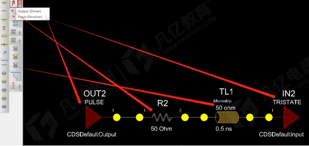
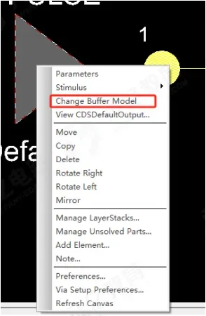
First build a link model. Set the transmission-line impedance to the usual 50 Ω, and replace the transmitter (tx) and receiver (rx) with 1.8 V high-speed models so the run represents a real signaling case.
Different Resistor Values Change the Waveform Sharply
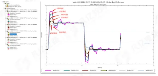
Six resistor values were swept to look at reflection: 0 Ω, 10 Ω, 20 Ω, 30 Ω, 40 Ω, and 50 Ω.
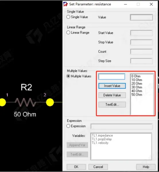
The differences show up immediately in the results:
- With no series resistor (0 Ω), the edge is too aggressive and overshoot is severe.
- At 10 Ω and 20 Ω, overshoot shrinks and the waveform improves.
- At 30 Ω the waveform is the most stable: neither overshoot nor a sluggish edge, and signal quality is the best of the set.
- At 40 Ω and 50 Ω the rise slows and undershoot appears, which is less desirable.
How to Choose the Resistor
A larger value is not automatically better, and a smaller value is not automatically better. The driver output resistance plus the series resistor should equal or approach the transmission-line impedance (50 Ω in the case above). That is the condition that cancels the reflection.
In practice, start with 22–30 Ω. Confirm the value in simulation, or swap values during bring-up until the waveform meets the requirement.
Why Many Current DDR Designs Have No External Series Resistor
Current DDR devices use ODT, which puts the termination inside the device and makes it programmable. ODT applies to the data lines. Address, control, and clock nets can still reflect if they are left unmatched.
Place the series resistor as close to the driver as possible. If it sits too far from the source, it no longer improves the signal.