For impedance matching, a series termination resistor can be placed at the source. Board space sometimes forces the part farther away, which raises a practical question: if the resistor is moved off the driver, or all the way to the receiver, can it still cancel reflection on the transmission line? The cases below check that placement.
1. Receiver Waveform with No Series Termination
Transmission line: 2000 mil.
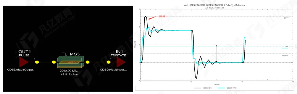
With no resistor, reflection is severe and the waveform is distorted.
2. Receiver Waveform with the Resistor Next to the Source
Transmission line: 2000 mil. Resistor: 33 Ω, placed next to the source.
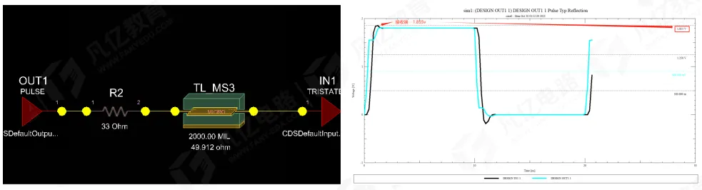
Compared with the unmatched case, reflection at the receiver is much lower. Overshoot and undershoot are no longer obvious.
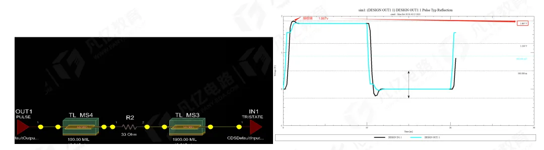
3. Resistor Offset 100 mil from the Source
Transmission line: 2000 mil. Resistor: 33 Ω. The signal leaves the source, travels 100 mil, then meets the series resistor.
4. Resistor Offset 300 mil from the Source
Transmission line: 2000 mil. Resistor: 33 Ω. The signal leaves the source, travels 300 mil, then meets the series resistor.
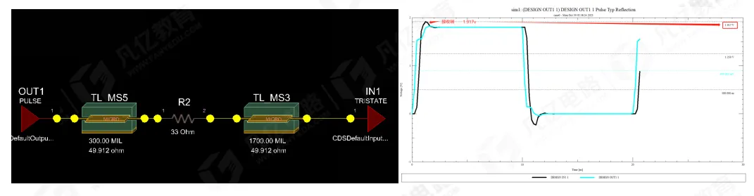
5. Resistor Offset 500 mil from the Source
Transmission line: 2000 mil. Resistor: 33 Ω. The signal leaves the source, travels 500 mil, then meets the series resistor.
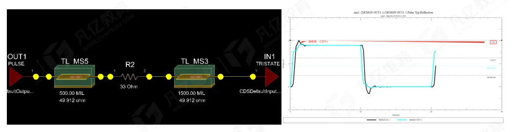
6. Resistor Offset 1000 mil from the Source
Transmission line: 2000 mil. Resistor: 33 Ω. The signal leaves the source, travels 1000 mil, then meets the series resistor.
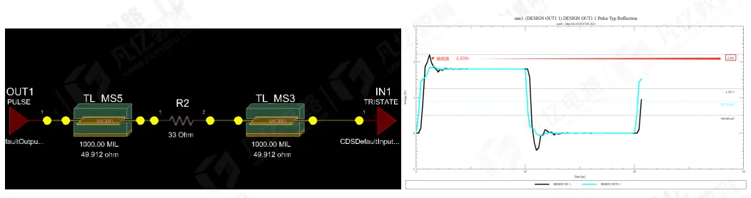
7. Resistor Placed Near the Receiver
Transmission line: 2000 mil. Resistor: 33 Ω. The signal leaves the source, travels 1000 mil, then meets the series resistor.
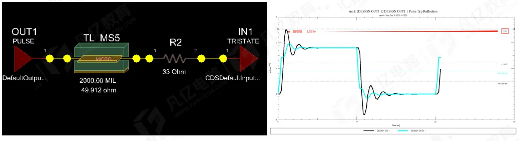
The waveforms show that the farther the series termination is from the driver, the worse the result. At 500 mil the signal already has visible ripple. With the resistor in the middle of the line, reflection becomes very clear. With the resistor at the receiver, the part no longer provides source-end matching, and reflection is severe.
During PCB placement, the series termination resistor must sit at the driver if it is to reduce reflection in a useful way.