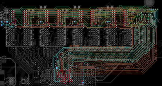
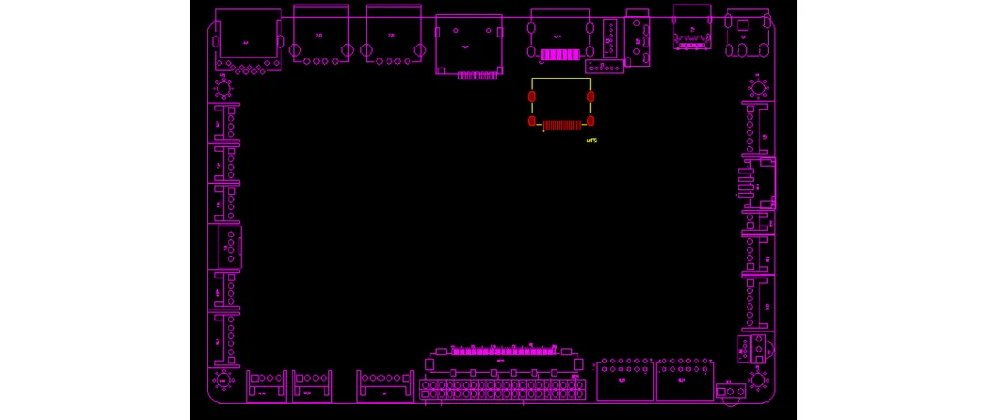
On the same PCB, pads, silkscreen, and 3D models may all look perfectly aligned, yet after importing the placement file an entire row of components appears offset. Many engineers first suspect the board outline or unit settings. In practice, the real culprit often hides in the footprint library: shift the origin even slightly, and every coordinate derived from that origin shifts with it.
The origin is not a casual crosshair left behind while drawing. It is the zero point of the footprint's local coordinate system. Once a component is placed on the PCB, the CAD tool uses this local origin to combine the footprint's X/Y and rotation with the board-level placement to generate the pick-and-place X, Y, and Rotation values.
Passing DRC does not guarantee correct assembly data. For reliable placement coordinates, the footprint's origin, pin-1 orientation, and zero-degree definition must follow a single, consistent rule across the entire library and the downstream manufacturing process.
The Body Center Is Not the Assembly Datum
For symmetric resistors and capacitors, placing the origin at the geometric center often works well. The footprint remains positionally stable when rotated and is easy for placement programs to interpret.
For irregular connectors, switches, and components with locating pins, however, the assembly datum might be defined by the body center, by a lead array center, or by a pick-up center recommended by the manufacturer. The pick-up center may not coincide with the pad array's geometric center.
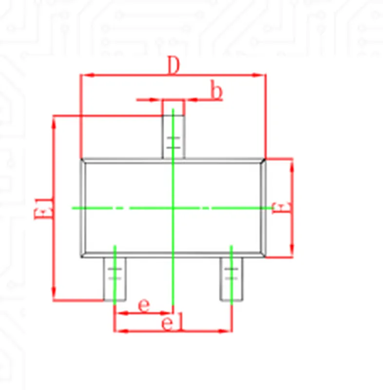
Figure 1 | SOT23 body dimensions and centerlines can be used to establish a stable local datum
The criterion is not whether the footprint "looks centered" on screen, but whether the same single reference point can be used consistently for CAD coordinate output, nozzle pick-up, and component placement on the machine.
Footprint libraries often contain multiple "origins" at once: a drawing origin, a footprint origin, and pad-end coordinates. The data that actually enters the placement file is typically the placement reference point, not the current drawing crosshair. When establishing library standards, explicitly name and separate these concepts. Avoid the common misunderstanding that a single "set origin" command defines all references. For devices with thermal pads or asymmetric mechanical features, consult the assembly drawing to verify whether the pick-up center deviates from the lead-array center.
When computing a geometric center for the origin, base it on the complete assembly object. If you only select the pads while excluding a locating peg or the body outline, the resulting center may be fine for routing but unsuitable for pick-up. Library standards should clearly state what geometry defines the center.
Pad Endpoint Coordinates Define How the Pattern Is Laid Out Around the Origin
The X and Y values in the footprint editor do more than set pad pitch; they define each pad endpoint's position relative to the footprint origin.
If the origin changes but the pad coordinates are not rebuilt according to the same rule, the footprint may still look correct by eye while its local coordinate system has silently switched to a different reference. Visual alignment alone is not sufficient.
During library review, record key pad coordinates and verify that the origin is exactly where you expect it, rather than relying on the apparent result after dragging with the mouse.
For bottom-side components, mirroring and rotation conventions add another layer of complexity. A "90°" rotation may be defined clockwise or counterclockwise in your CAD display, in the placement file, and on the machine. Even with a correct origin, inconsistent angle conventions can cause a batch-wide orientation error. Provide coordinate samples that include both top and bottom components, and include at least one clearly polarized device (such as a diode or IC) as an orientation reference. Lock units to either millimeters or mils to avoid compounding origin issues with unit conversions.
Panelization adds additional references: the sub-board origin, the panel origin, and the overall manufacturing datum. If a single-board's coordinates are correct but the panel import is offset, verify each level of the coordinate hierarchy in turn, rather than rushing to alter footprints.
If Zero Degrees Is Wrong, the Entire Rotation Set Is Misaligned
The Rotation in a placement file usually references the footprint's zero-degree direction. If the library defines 0° as pointing to the right, but the factory database defines 0° as pin-1 pointing up, importing the data will produce a consistent 90° or 180° difference across the affected components.
Packages such as SOP, QFN, and other polarized devices must have the pin-1 marker, silkscreen orientation, and zero-degree direction all clearly defined. Do not align only the geometric center and leave direction ambiguous.
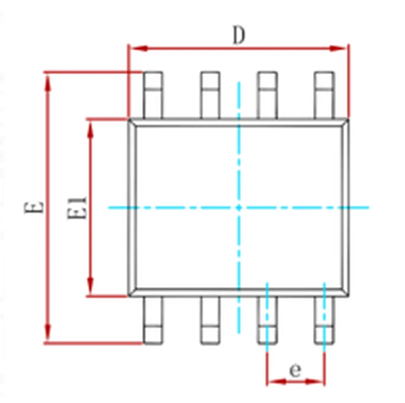
Figure 2 | SOP footprints should be centered geometrically and retain explicit pin-1 and orientation definitions
After changing a footprint origin or orientation, place a fresh test instance and regenerate the placement coordinates. Do not reuse old placement files.
When a library is modified, existing board instances may not automatically update. Different tools may allow preserving local edits, updating only the pads, or resetting all attributes. After correcting an origin, verify that the components in the design actually reference the new revision and re-export the assembly data. If older projects must remain traceable for manufacturing, record the library version and modification date instead of overwriting history and explaining old coordinates using only the current library.
For alternate parts using the same footprint, confirm that a shared origin remains valid if the body outline or pick-up region differs. Pad compatibility does not guarantee identical assembly datums. Alternate-part reviews must include placement data checks, not just PCB land pattern comparisons.
Close the Loop on One Component Before Release
Choose one component with a known position and clear orientation. Record its X, Y, and Rotation on the board, then export the placement file and compare each item line by line.
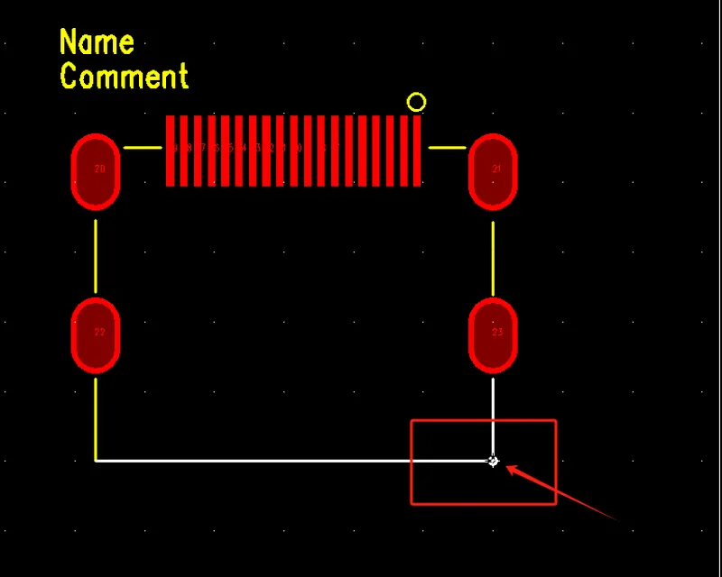
Figure 3 | The footprint reference point on the board should match both the coordinate file and the placement direction
When viewing the assembly preview, check whether the reference point lies within the component body, whether the center remains stable after a 90° rotation, and whether pin-1 points in the expected direction.
If coordinate deviations occur only within a specific footprint family, go back to the library, fix the origin, and update all instances on the board. Do not compensate part-by-part in the factory's coordinate table.
Before volume production, prepare a small coordinate acceptance checklist capturing, for a handful of representative footprints, the following: designator, board X/Y, footprint origin location, 0° direction, pin-1 direction, top/bottom layer, and the corresponding values as read by the placement file. Ask the CAM or SMT team to return an import preview once to confirm that the board outline and manufacturing datum also align. This simple closed-loop process can simultaneously expose origin, mirroring, angle, unit, and "library update not applied" issues.
After the loop is validated, store the sample files and import screenshots alongside the footprint library. After software upgrades or output template changes, the team can run a quick regression using the same component without waiting for factory feedback.
Conclusion
Shifting a footprint origin does not change whether copper is connected, but it does change how manufacturing interprets the component's position. That makes origin errors subtle—and best eliminated at the library stage.
Document the origin, pin-1 marker, and zero-degree direction in the footprint acceptance checklist, and close the loop with a known component's coordinates. This approach is far more reliable than last-minute manual corrections to the placement table before mass production.