After the negative supply is removed, an AC signal still needs room to swing both above and below its DC operating point.
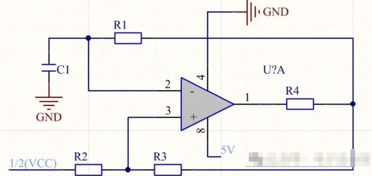
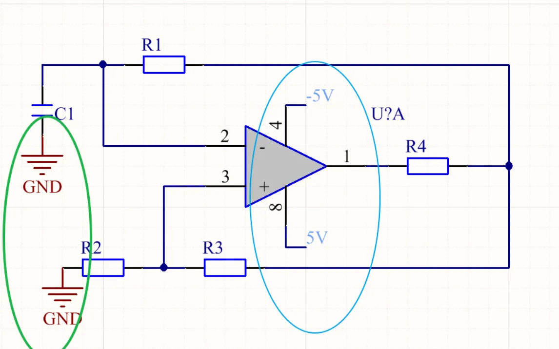
A dual-supply circuit lets the signal swing above and below 0 V. After the change to a single supply, 0 V is already the lower supply limit, so the negative half-cycle has no room. Midpoint bias first lifts the signal to near the middle of the supply so it can still move both upward and downward.
If the op-amp's negative supply pin is simply moved from a negative voltage to GND, the circuit can power up, but the output sits near ground or keeps only the upper half of the waveform. The gain has not changed. The problem is the signal's DC operating point.
This article covers one action only: when converting to a single supply, the input and feedback reference points must both be moved to the midpoint bias.
With Dual Supplies, 0 V Sits in the Middle of the Signal
When an op-amp runs from positive and negative supplies, 0 V is spaced away from both supply rails. The AC signal varies around 0 V, so both the positive and negative half-cycles have room.
After the supply becomes 0 V to VCC, 0 V is the lowest potential. If the signal still swings around 0 V, the negative half-cycle runs into the supply boundary.
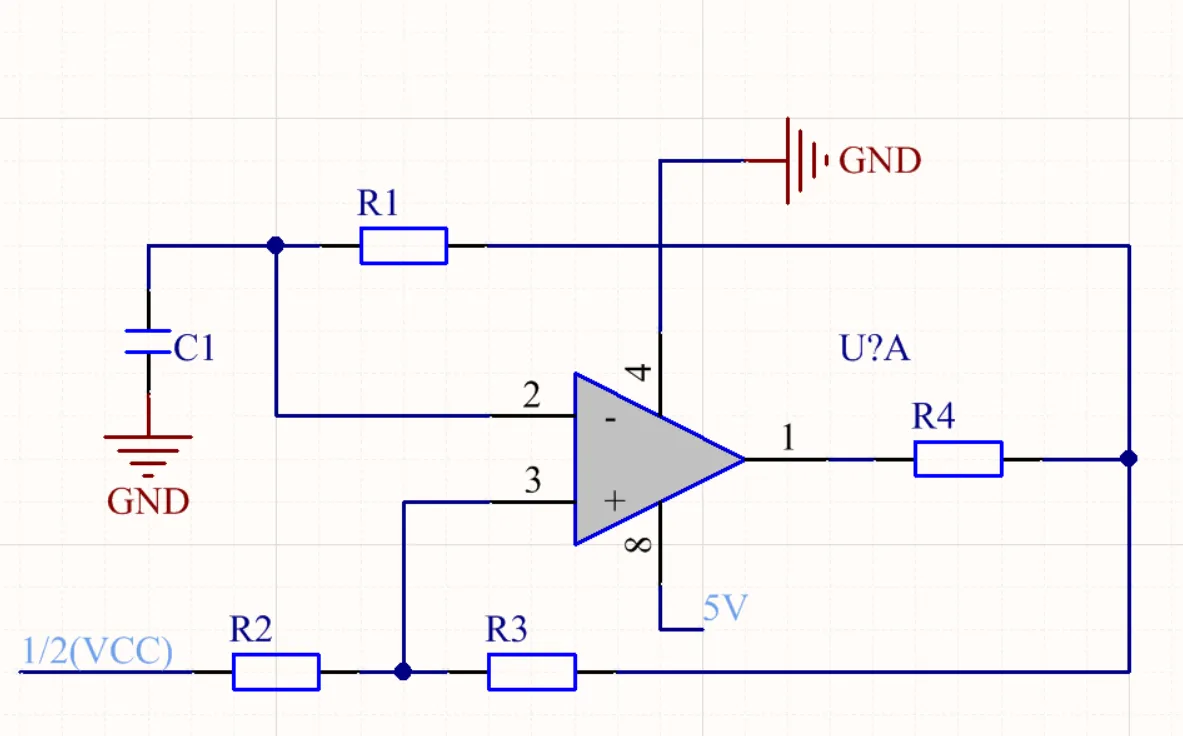
Midpoint Bias Gives the AC Signal Room on Both Sides
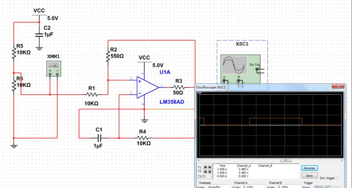
Two resistors can first divide out a midpoint voltage, commonly written as VBIAS. It acts as the new signal ground: with no AC input, the op-amp input and output first sit at this level.
The AC signal is then superimposed on VBIAS, so it can swing both upward and downward within the single-supply range.
Input, Feedback, and the Next Stage Must Share the Same Reference
- Input: after coupling, the signal must be pulled to VBIAS.
- Feedback: the reference end of the feedback network must also return to VBIAS.
- Next stage: if the following stage is still referenced to GND, decide whether to AC-couple or re-bias it.
If VBIAS is created only with large divider resistors, feedback current or load current can pull that node around. A bypass capacitor can make the node more stable for AC. A buffer may also be needed when the load is heavy.
Check Only Two Device Limits at the End
- Check the input common-mode range and confirm that VBIAS plus the signal peak still stays inside the allowed interval.
- Check the output swing and confirm that the output will not hit the upper or lower supply rail.
Set the Operating Point First, Then Calculate Gain
Converting from dual supply to single supply is, in essence, giving the signal a new DC operating point. After the midpoint bias is set, check the common-mode range and the output swing.