Thermostats that integrate the heater and the temperature sensor into the same physical element can be remarkably efficient. When the heat-generating element also functions as the sensor, any power drawn by the control loop tends to appear as useful heat rather than wasted dissipation. When a transistor itself serves as the combined sensor and heater, high efficiency is achievable in both linear and pulsed operating modes.
Hot-wire thermostats built from a thin copper wire also integrate the sensor and heater. However, unlike the transistor-as-heater approach, the hot wire remains separate from the power transfer device that regulates current. In a conventional linear controller, the pass device must drop a variable portion of the supply voltage to regulate wire temperature. That voltage drop translates directly into dissipation in the pass device, which does not contribute to heating the wire. The resulting power loss erodes overall efficiency. Avoiding that linear loss is what makes a switching-mode control strategy so compelling for a hot-wire thermostat.
Switch-Mode Thermostat Concept
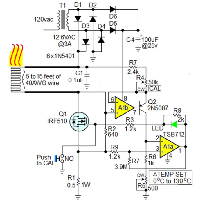
The switch-mode implementation retains the same copper-wire sensor/heater and nearly the same interface as a linear hot-wire thermostat, but it changes how the pass element is driven. Instead of forcing the pass element to operate in its linear region, the amplifier adds positive feedback to create a comparator-like action with hysteresis. The MOSFET is then driven fully on or fully off based on the error signal, allowing the wire to be heated efficiently via pulse-width control rather than through continuous linear regulation.
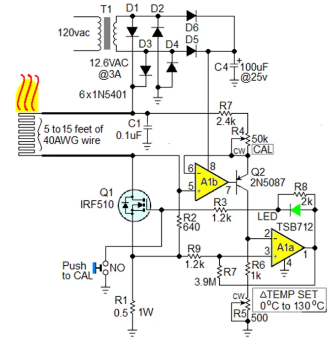
Figure 1 | A switch-mode thermostat efficiently heats a copper-wire integrated sensor/heater.
The copper wire serves as both the heater and the temperature sensor: its temperature-dependent resistance provides the feedback signal, and the same current that produces heating produces the resistance change. The key difference from a linear controller lies in how the error signal is used to command the MOSFET gate. With the added positive feedback resistor (R7) around the amplifier A1a, the control loop exhibits hysteresis, forcing Q1 to operate only in two states—fully enhanced or completely off—rather than anywhere in between.
Baseline Linear Hot-Wire Thermostat
For comparison, consider a linear-mode hot-wire thermostat using a thin copper wire, such as a 40 AWG element, whose positive temperature coefficient of resistance (TCR) provides a convenient temperature-sensing mechanism. The same wire, driven by I2R heating, serves as the heater.
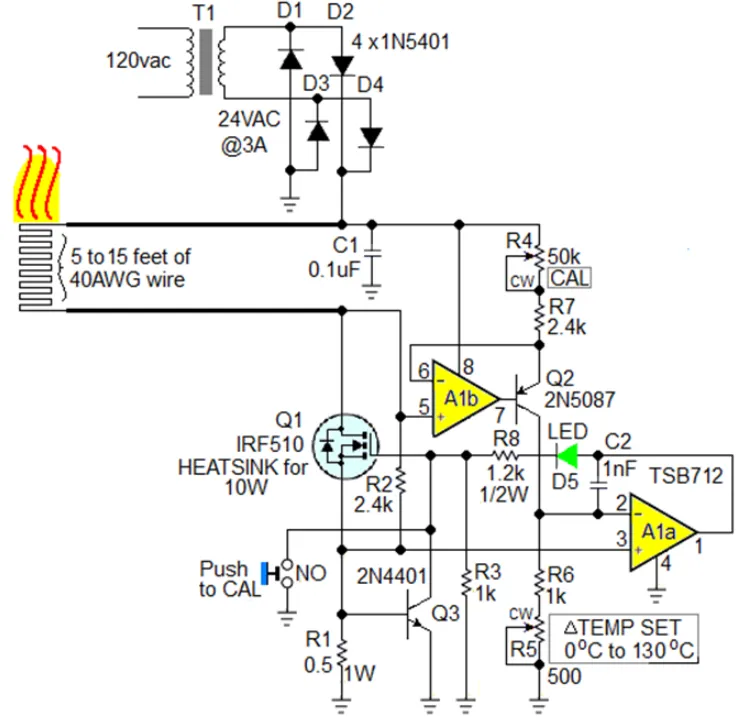
Figure 2 | In a linear hot-wire thermostat, a 40 AWG copper wire's positive TCR provides sensing while I2R heating provides the heat source.
In the linear design, the temperature-dependent voltage difference between R1 and the divider R5+R6 is amplified by A1a and applied to Q1's gate. The amplifier forces Q1 to drop exactly the voltage needed to make the hot-wire temperature match the setpoint defined at R5. This approach achieves tight temperature control, but it incurs heavy dissipation in Q1—up to 10 W—because Q1 must continuously absorb the difference between the supply and the wire voltage. That energy is not delivered to the wire and therefore does not contribute to heating, which limits the system's efficiency.
Why Switching Improves Efficiency
In the switch-mode circuit, the op amp, together with R7, implements a controlled hysteresis band around the setpoint. When the measured hot-wire temperature (derived from its resistance) falls below the lower threshold, A1a drives Q1 fully on. Current rises rapidly, heating the wire via I2R power. As the temperature rises and the sensed voltage crosses the upper threshold, the amplifier flips state and turns Q1 fully off. The wire then cools slightly, and the cycle repeats. This is a classic bang-bang thermostat with hysteresis.
This change in control strategy has two major effects on power flow and efficiency:
- When Q1 is on, it operates as a low-resistance switch. Conduction loss is primarily I2 multiplied by Q1's RDS(on), which can be made small. Most of the power is delivered to the hot wire, where it produces useful heat.
- When Q1 is off, it dissipates negligible power. The average loss in Q1 over time is therefore much lower than in a linear regulator, where Q1 continuously drops voltage.
In practical terms, this reduces or eliminates the need for a heatsink on Q1. The switch-mode circuit can also operate from a lower supply voltage than the linear version for the same target wire temperature because there is no need to reserve headroom for a linear drop across Q1. The net effect is a substantial improvement in end-to-end efficiency.
Measured heating efficiency depends on the length (and thus resistance) of the hot wire. With a 5 ft wire, efficiency is about 83%, rising to approximately 94% with a 15 ft wire. The improvement with longer wire stems from the higher wire resistance, which commands a larger share of the voltage and power when Q1 is fully on, leaving less to be lost across Q1's RDS(on). By contrast, the linear version tops out at roughly 50% efficiency because half or more of the input power can be burned in the pass device at any given operating point.
Control Loop Dynamics and Hysteresis
The positive feedback resistor R7 creates a defined separation between the turn-on and turn-off thresholds, preventing rapid chatter around the setpoint. Without hysteresis, a very small perturbation in sensing voltage could cause Q1 to toggle at high frequency, increasing switching losses and potentially exciting thermal or electrical oscillations. With properly chosen R7 and loop gains, the cycle repeats at a rate set by the wire's thermal time constant, the supply, and the on-state current—typically in the low-duty-cycle regime required to hold the desired temperature.
The result is tight temperature regulation with efficient use of input power. The wire itself remains the sensing element: as it heats, its resistance rises; the control loop translates that resistance change into a voltage that is compared against the setpoint divider (R5+R6). The op amp's output saturates in one of two states, so Q1 never lingers in the linear region where losses would escalate.
Calibration Procedure
Both the switch-mode and linear versions share the same calibration sequence. Performing this sequence ensures that the resistance-based sensing aligns with the desired temperature setpoint and that the hysteresis thresholds are positioned appropriately around the target.
-
Before the first power-up, allow the sensor/heater wire to fully equilibrate to room temperature.
-
Set R4 and R5 fully counterclockwise (CCW).
-
Press and hold the CAL NC button.
-
Apply power to the circuit.
-
Slowly rotate R4 clockwise until the LED blinks for the first time.
-
Release the CAL button.
After calibration, R5 can be used to fine-tune the temperature setpoint. Because the switch-mode loop uses hysteresis, a slight, controlled temperature ripple around the setpoint is expected and is typically much smaller than the thermal time constant of the application would allow.
Practical Design Notes
The copper wire's positive temperature coefficient is central to this thermostat architecture. As current heats the wire, its resistance increases, providing a monotonic feedback signal that the control loop can use to stabilize temperature. Because the wire is both the heater and sensor, there are no thermal interface errors between a separate heater and sensor; the loop senses exactly the temperature at the point of heating, improving accuracy and responsiveness.
Several practical considerations help ensure robust performance:
- Wire selection and length: A thin copper wire (e.g., 40 AWG) provides a high resistance per unit length and a strong I2R heating effect. Longer lengths increase total resistance, shifting more of the supply voltage to the wire and improving efficiency when Q1 is fully on. The 83% to 94% efficiency figures correspond to 5 ft to 15 ft lengths, respectively.
- Pass device choice: The MOSFET's RDS(on) sets conduction loss during on-time. Select a device with low RDS(on) at the expected operating current to minimize losses. Because the device switches between fully on and off, switching losses and gate-drive requirements should be considered, but they are generally modest at the low frequencies dictated by the thermal dynamics.
- Hysteresis design: The positive feedback resistor R7 sets hysteresis width. Too little hysteresis can cause chatter and increased switching loss; too much can widen the temperature band excessively. Choose R7 to balance stability and temperature regulation tightness for the specific wire and application.
- Supply headroom: Unlike the linear design, the switch-mode version does not need a large voltage margin for regulation across Q1. This allows operation from a lower supply for the same target temperature, reducing stress on both the wire and the pass device.
- Sensing integrity: Route the sense connections so they measure the true voltage across the heated section of wire, not including extraneous lead or connector drops. Consistent, low-resistance connections help maintain a precise relationship between measured voltage and temperature.
- Thermal and mechanical stability: Ensure the wire is mounted to minimize drafts and mechanical vibration, both of which can modulate heat loss and cause minor temperature fluctuations. The control loop's hysteresis and thermal time constants will generally smooth such effects.
Compared with the linear counterpart, the switch-mode hot-wire thermostat eliminates substantial wasted heat in the pass device. In practice, this means Q1 can often run without a heatsink and the entire circuit can operate from a lower supply voltage for a given temperature target. The measured efficiency climbs from around 50% for the linear approach to 83–94% for the switch-mode design, depending on wire length and resistance. The only change required to achieve this improvement is the addition of a positive feedback path that reconfigures the op amp from a linear error amplifier into a hysteretic comparator driving the pass element in a fully on/off manner.
For applications where compactness, energy efficiency, and precise thermal control are important, this small change delivers a substantial performance gain while preserving the simplicity and robustness of a hot-wire thermostat.