Touch keys are now widely used. This article provides an introductory overview of capacitive touch sensing and its basic operating principles.
01 | Overview
Capacitive touch sensing detects the presence or proximity of a finger by measuring changes in capacitance. With capacitive sensing, mechanical switches and knobs can be replaced by aesthetically pleasing buttons, sliders, and wheels to address issues such as:
- Wear and reduced reliability after prolonged use
- Gaps between the front panel and keys that allow moisture ingress and cause faults
- The need to apply physical force to actuate a switch
- Added cost due to front-panel cutouts
- Limited fixed key shapes
Capacitive touch supports five sensor types: keys, proximity sensing, wheels, sliders, and touch panels. It also supports multiple cover materials. Typical advantages include low power consumption, robust sensing algorithms, strong noise immunity, and support for waterproofing.
02 | Basic Principle
Typical capacitive touch sensors use copper areas on the PCB as electrodes. The top surface is covered by a nonconductive protective layer such as glass or plastic bonded to the PCB with adhesive. A guard or grid ground is often placed around the sensors.
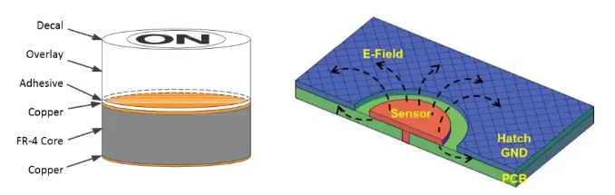
Based on the measured capacitance type, capacitive touch sensing is classified as self-capacitance detection (measuring capacitance between a single electrode and ground) or mutual-capacitance detection (measuring capacitance between a pair of electrodes).
2.1 Self-capacitance Detection
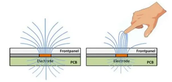
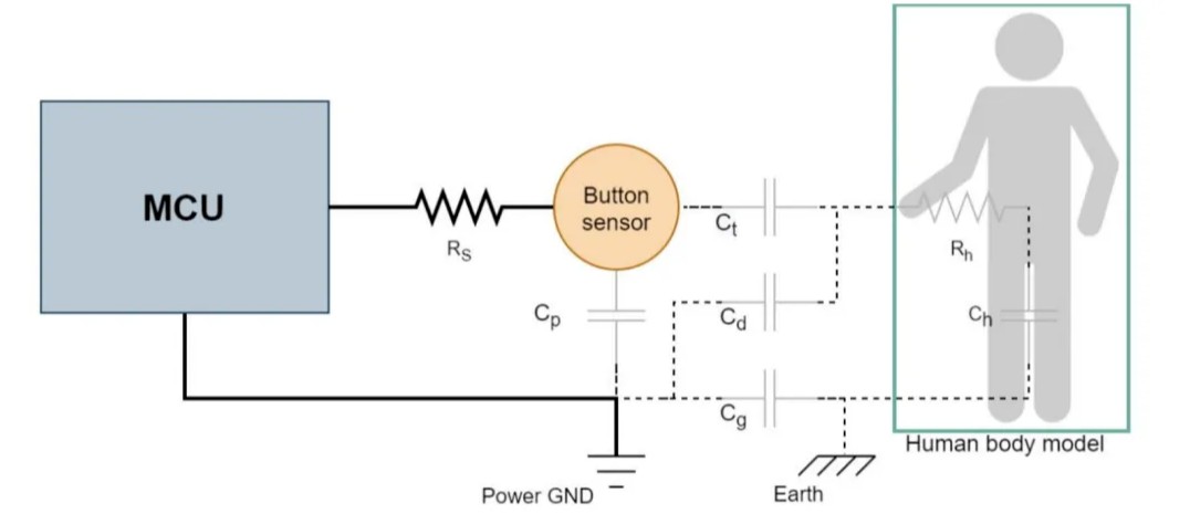
For a simple single key, the self-capacitance detection model is shown below. Self-capacitance sensing uses a single copper electrode (receive electrode Rx) to detect the electrode-to-ground capacitance change. The key's initial capacitance to ground is Cp. When a human finger touches, the loop is influenced by Ct, Ch, and Cg, causing the electrode-to-ground capacitance to increase.
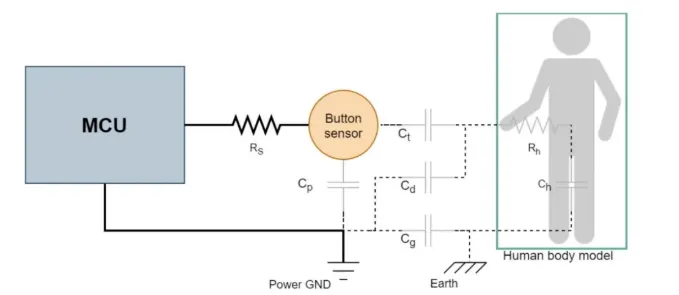
Note: Solid lines indicate actual wiring; dashed lines indicate non-physical connections. Grey components represent equivalent capacitances or resistances.
- Rh: Human body resistance
- Rs: Series resistor, recommended value 470 Ω
- Cp: Parasitic capacitance from the key and its traces to system ground
- Cg: Capacitance between system ground and earth. For battery-powered applications, approximately 1 pF; for earth-grounded applications, it may be effectively shorted.
- Ch: Series capacitance between the human body and earth
- Ct: Capacitance formed between the electrode and the fingertip (similar to a parallel-plate capacitor)
- Cd: Capacitance between the hand and system ground
For simplified analysis, Rh and Rs effects are ignored. The electrode-to-ground equivalent capacitance is given by Formula 1-1 (see image). Sensitivity can be defined as the ratio of the touch-induced capacitance change to the baseline capacitance (also shown in Formula 1-1). Since Ch is large compared with Cg and Ct, Ch can be neglected. When the ground plane is sparse, Cd is small and Cg + Cd can be approximated as Cg.
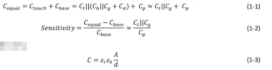
Where:
- A: Contact area between fingertip and the sensor cover
- d: Thickness of the cover layer
- ε0: Permittivity of free space
- εr: Relative permittivity of the cover layer
From Formulas 1-2 and 1-3, methods to improve sensitivity include:
- Reduce the cover thickness and/or increase the cover material's εr to increase Ct
- Reduce the density of the grid ground or increase the PCB thickness to lower Cp
- Since Ct and Cg can be of similar magnitude, connecting system ground to earth in a reasonable way increases Cg
- Increase electrode area sensibly — raising the fingertip contact area A to increase Ct
Note that electrode area cannot be increased indefinitely to raise sensitivity. The effective parallel-plate capacitance area is limited by the fingertip contact area, and excessively large electrodes increase Cp, which can reduce sensitivity.
2.2 Mutual-capacitance Detection
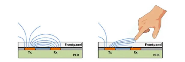
Mutual-capacitance sensing uses paired copper electrodes (transmit Tx and receive Rx) to detect capacitance changes between the two electrodes. A major advantage of mutual-capacitance detection is that the parasitic capacitance from the key to system ground (Cp) can be largely ignored. For a single-key example, the detection model is shown below. When a finger touches, CRT is effectively split into two capacitors (2·CRT) and additional terms CRTt, Ct, Ch, and Cg are introduced. Ultimately, the capacitance between the electrode pair decreases.
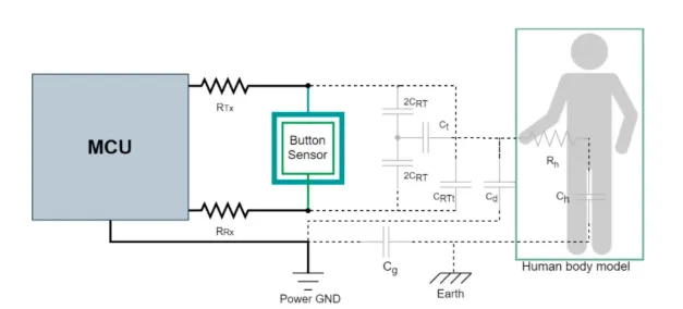
Note: Solid lines indicate actual wiring; dashed lines indicate non-physical connections. Grey components represent equivalent capacitances or resistances.
- CRTt: Parallel capacitance introduced between Rx and Tx by the touching finger
- CRT: Baseline capacitance between Rx and Tx; when touched, it becomes two capacitors of value 2·CRT in the equivalent model
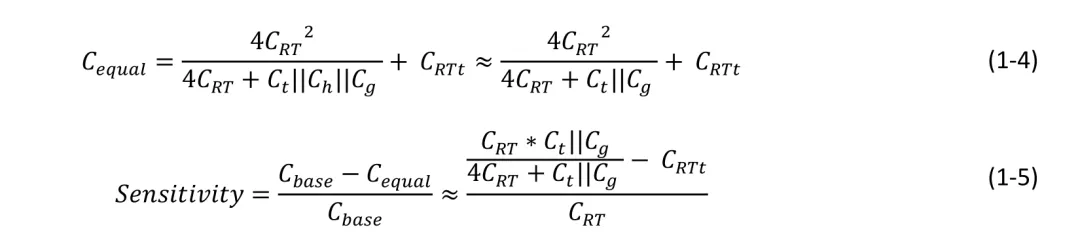
The equivalent capacitance between Tx and Rx is given by Formula 1-4, and sensitivity is defined as the ratio of the touch-induced capacitance change to the baseline capacitance (Formula 1-5).
For mutual-capacitance sensing, main ways to increase sensitivity are:
- Reduce the cover thickness
- Increase the spacing between Tx and Rx. Note: Increasing Tx–Rx spacing reduces CRT and can increase detection distance (effectively increasing sensitivity), but if a fingertip cannot simultaneously overlap both Tx and Rx, sensitivity may decrease.
In general, finger touches produce capacitance changes on the order of about 1 pF for both self- and mutual-capacitance sensing. However, the baseline (pre-touch) capacitance for self-capacitance sensors is typically higher than that for mutual-capacitance sensors. Therefore, mutual-capacitance designs tend to offer higher sensitivity relative to their baseline but are also more susceptible to noise.
From an application standpoint, self-capacitance schemes are widely used due to simpler structure, while mutual-capacitance schemes are often used for matrix key arrays where the supported key count far exceeds the number of IO pins available for self-capacitance keys. A comparison between the two schemes is shown in the figure below.