










-
 10:07
10:07
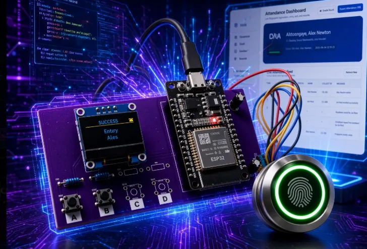
ESP32 Fingerprint Attendance PCB: Reliable 2-Layer Design Ends Breadboard Failures
This video follows the complete development journey of an ESP32-based fingerprint recognition system, from a functional breadboard prototype to a finished custom PCB. It covers schematic capture in EasyEDA, conversion to a double-sided layout for hand assembly, and key placement and routing decisions for the ESP32, OLED, R503 fingerprint sensor, decoupling capacitors, UART, and I²C interfaces. The firmware integration includes Wi-Fi connectivity, fingerprint enrollment and verification, OLED status animations, and a responsive web dashboard with CSV export. Live demonstrations show 1:1 verification, 1:N searches, and real-time dashboard updates. The final assembled board demonstrates how thoughtful PCB layout, firmware integration, and mechanical design can turn a working prototype into a reliable, technician-ready system.
-
 10:53
10:53
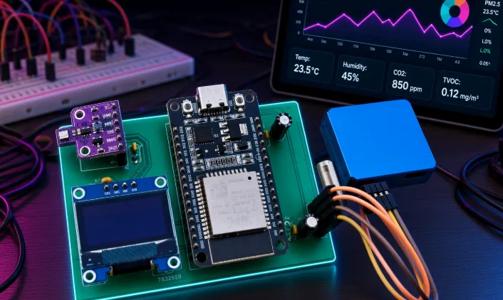
ESP32 Air Monitor PCB: Reliable Custom Board for Clean Sensor Data
This video showcases the complete development journey of an ESP32-based particulate matter and air quality monitoring system, from sensor integration and custom PCB design to a fully functional monitoring interface. The device combines a PMS7003 particle sensor, BME680 environmental sensor, OLED display, and ESP32 to deliver real-time air quality data through both local and browser-based interfaces. Viewers see an interactive IAQ gauge, live PM trend graphs, data logging with Excel export, and configurable alerts. The video also highlights critical PCB design considerations, including component placement, power integrity, sensor airflow, and common 2-layer board pitfalls. With clean boards manufactured in just three days, the project demonstrates how thoughtful PCB design and DFM practices can accelerate reliable IoT sensor development.
-
 10:04
10:04
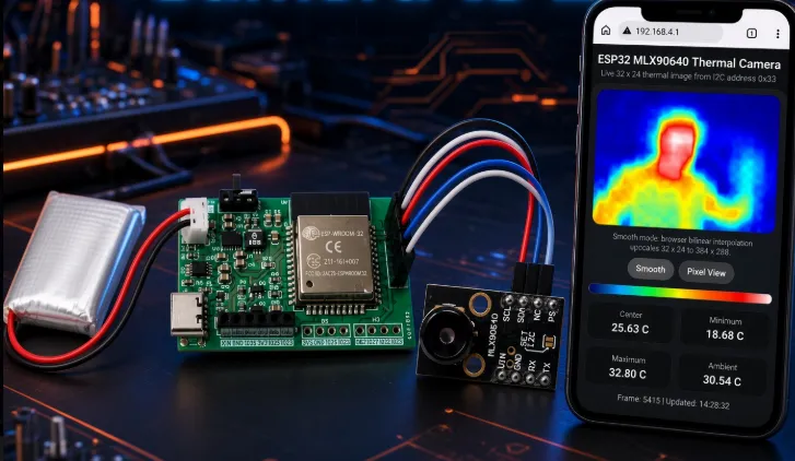
ESP32 Thermal Camera PCB: How AIVON Rapid Prototyping Delivered a Working Handheld Tool
This video showcases the complete development journey of an ESP32-based MLX90640 thermal camera board, from system architecture and PCB design to manufacturing and software integration. The project uses a compact 2-layer FR-4 design with front-side component placement, a TPS63020 buck-boost power system, BQ24092D battery charger, and a clean I²C connection to the MLX90640 thermal sensor. Viewers see how the sensor’s 32 × 24 data matrix is processed by the ESP32 into a live interpolated heatmap accessible through a web interface. The video also highlights practical DFM lessons, including power integrity, solder-mask openings, via treatment, panel stamp holes, and component assembly quality. By demonstrating the finished AIVON boards and real-world battery and Wi-Fi testing, the project shows how consistent PCB manufacturing can reduce hardware debugging and accelerate IoT product development.
-
 10:41
10:41
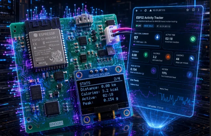
Custom 4-Layer PCB Powers Reliable ESP32 Pocket Motion Tracker
This video showcases the complete development journey of a custom 4-layer ESP32 activity tracker, from system architecture and PCB design to manufacturing and real-world testing. The project combines an ESP32-S3 with a BNO085-class IMU, multiple OLED information pages, and a live web dashboard for tracking activity goals, cadence, and motion levels. It also explores the power architecture, including USB-C charging, buck-boost regulation, and noise-conscious PCB layout for stable sensor performance. Viewers gain insight into stack-up selection, PCB layout, fabrication challenges, and DFM practices that support reliable first-article production. Outdoor testing demonstrates how the hardware, firmware, and manufacturing decisions come together to deliver a functional and dependable wearable device.
-
 09:33
09:33
Custom Video Interface PCB: Reliable Prototyping for Discrete Logic Displays
This video documents Spencer’s multi-month journey to build a working video system using discrete logic ICs, from early breadboard experiments to displaying text on a real monitor. The project evolves from a simple timing circuit using a handful of boards and ICs into a more structured 27-IC design simulated in Logisim, featuring cascaded counters for horizontal and vertical timing. It explains how RAM-stored pixel data is converted from 16-bit words into a one-bit video stream while generating the required sync and blanking signals. Through multiple physical rebuilds, testing challenges, and eventual success, the video highlights the practical realities of translating digital logic simulations into functioning hardware and the persistence required to troubleshoot real-world signal and timing issues.


