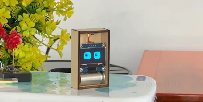
There's something special about a tiny gadget that sits on your desk and actually feels alive. Not another blinking LED clock or sterile weather widget—something with personality. The Desk Buddy Pet Robot does exactly that. It stares at you with expressive animated eyes, shows the time and date, pulls live weather and temperature, offers a world clock, and even updates from the cloud. A single touch changes the display modes; a long press swaps the eye animations. Rechargeable, compact, and quietly charming, it turns a plain workspace into a little companion zone.
The creator Pro maker 101 behind this build wanted more than a one-off breadboard toy. They wanted a device that could live on any desk without looking like a prototype, stay powered for days, respond reliably to touch, and keep its Wi-Fi link solid for weather data. That ambition is exactly where solid PCB design and manufacturing stop being optional and start becoming the difference between "cool weekend project"and "this actually works every day."
Cool Features That Make This Desk Buddy Feel Alive
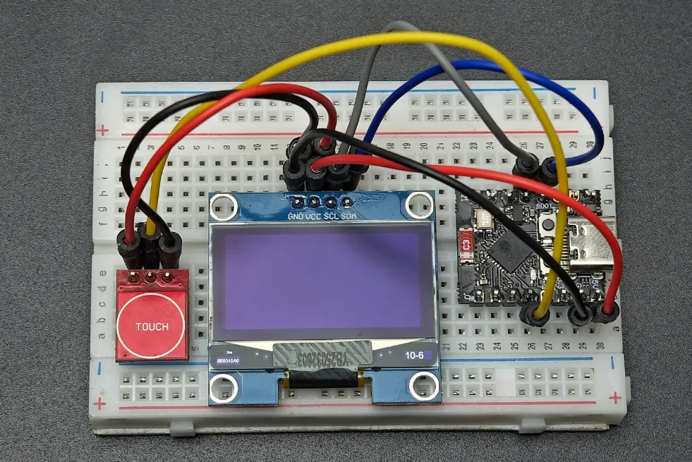
Watching the finished robot come to life is the best part. The OLED face doesn't just sit there—it blinks, looks around, and shifts expressions so the little device feels like it's paying attention. Single taps cycle through the useful screens: local time and date, current weather status and temperature, a world clock view, and cloud-connected updates. Long-press the TTP223 capacitive touch sensor and the eyes switch animation styles, giving the robot a different personality on demand.
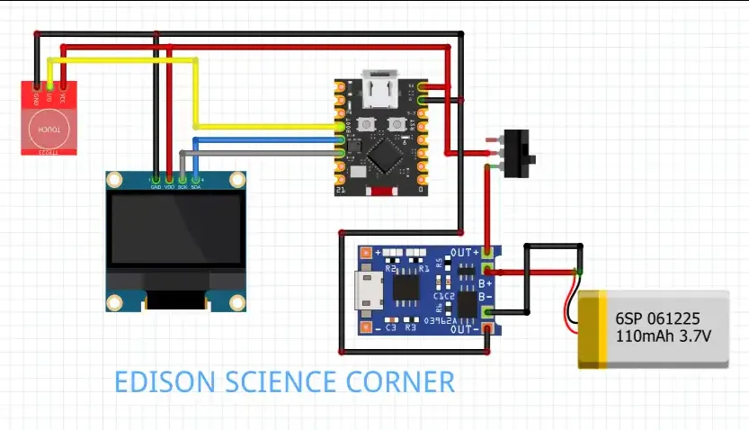
Under the hood the brain is an ESP32-C3 SuperMini—small, cheap, Wi-Fi capable, and more than enough for the job.
A rechargeable LiPo battery keeps it cordless, the OLED delivers the visual charm, and the touch sensor replaces clunky buttons so the whole package stays clean and modern. Everything fits inside a compact 3D-printed enclosure that looks intentional rather than improvised.
Figure: Desk Buddy Pet Robot Components
The real "wow"moments happen in daily use. You glance over while working and the eyes are already looking back. You get a quick weather check without unlocking your phone. The touch response is immediate and satisfying. That combination of useful information and playful presence is what makes people say "this has to live on every desk."
The creator iterated the software side carefully—OpenWeatherMap API integration, smooth animation timing, and mode switching that feels natural. But hardware is what decides whether those software features stay reliable once the case is closed and the device is used for weeks.
DFM Checklist for Compact Battery-Powered Desk Companions
|
Check Item |
Why It Matters for This Project |
Recommended Action |
|---|---|---|
|
Antenna keep-out zone |
ESP32-C3 Wi-Fi range drops if copper is nearby |
Clear 5–8 mm zone, no ground under antenna |
|
Board thickness |
Must fit tight 3D enclosure |
1.0 mm or thinner preferred |
|
Ground plane continuity |
Prevents brown-outs during Wi-Fi TX |
Solid pour under MCU, short return paths |
|
Battery pad & charger placement |
Avoid noise into I2C and touch lines |
Separate analog/digital, add decoupling |
|
Connector orientation & strain |
Repeated opening of the case |
Align connectors with case openings |
|
Pad size & finish for hand/reflow |
Small OLED and touch pads |
ENIG + slightly enlarged pads |
|
Via size near connectors |
Mechanical stress during assembly |
Avoid microvias under high-stress areas |
Potential Challenges in Building a Compact Rechargeable Desk Robot
Compact battery-powered projects like this naturally come with several design considerations that smart makers anticipate early.
Tight enclosure space often makes hand-wired modules tricky — loose connections or bulky Dupont wires can create reliability concerns once everything is squeezed into a 3D-printed case. The OLED and touch sensor leads become potential stress points during repeated handling.
Wi-Fi performance is another common area of focus. The ESP32-C3's PCB antenna is sensitive to nearby components, ground planes, or the battery, which can affect signal stability for cloud weather updates.
Power delivery during Wi-Fi activity also needs careful attention. Transmit bursts create current spikes that can impact stability without proper decoupling and a solid ground return path. Charging circuitry must be isolated to avoid introducing noise into I2C lines or the touch sensor.
Capacitive touch reliability in a plastic enclosure can vary with hand position or board flex, and consistent assembly across multiple units benefits greatly from a clean PCB layout rather than individual wiring.
These are the kinds of practical realities that experienced builders plan for — and addressing them early through thoughtful PCB design prevents small issues from becoming big frustrations later.
How AIVON's Custom PCB Turned the Vision into a Reliable Product
This is where the story turns from "promising prototype"into "desk-ready product."
The creator brought the schematic and early layout to AIVON. Instead of just quoting a board, the engineering review team looked at the actual use case: a battery-powered, always-on, Wi-Fi desk companion that had to fit a tight 3D-printed shell and survive daily handling.
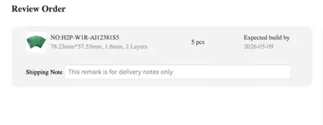
They suggested a 1.0 mm board thickness so the stack height stayed low. They pushed for ENIG finish so the small battery pads and OLED header would solder cleanly and stay reliable over many charge cycles. The biggest win was the ground-plane and antenna-keepout recommendations. A solid copper pour under the ESP32, combined with a clear keep-out zone around the antenna, immediately improved Wi-Fi stability. Short, direct I2C traces to the OLED reduced noise and eliminated the occasional display flicker that had appeared on the wired version.
DFM checks caught several small but critical issues: pad sizes that were too aggressive for reliable soldering, via placement that would have caused yield problems, and connector orientations that made enclosure assembly awkward. Those fixes were made before the first production batch, saving weeks of rework.
The boards arrived quickly, the free engineering review comments were practical, and the finished PCBs assembled cleanly. Suddenly the device no longer felt like a collection of modules held together by hope. It felt like a real product—compact, consistent, and ready for everyday use. The animated eyes stayed smooth, the weather updates stayed reliable, and the touch response stayed crisp because the hardware foundation was solid.
That is the quiet power of a good manufacturing partner: they don't take the credit for the creative idea, but they make sure the idea can actually live on people's desks without constant babysitting.
Inside the Custom PCB: Design Choices That Actually Mattered
To move from hand-wired modules to a production-ready product, a custom PCB was essential. Here's what the final board looked like:
|
Parameter |
Specification |
|---|---|
|
Layers |
2-layer |
|
Material |
FR-4, Tg 130–140 °C |
|
Board Thickness |
1.0 mm (kept thin for enclosure fit) |
|
Copper Weight |
1 oz |
|
Surface Finish |
ENIG (reliable for small pads & battery) |
|
Via Type |
Through-hole, 0.3 mm drill |
|
Min Trace/Space |
0.15 mm / 0.15 mm |
|
Special Requirements |
Solid ground plane under ESP32, antenna keep-out zone, short I2C runs for OLED |
The layout prioritized three things: keeping the ESP32-C3 SuperMini's onboard antenna clear of copper and plastic, routing the battery and charging section with proper decoupling, and placing the OLED and TTP223 connectors so assembly stays simple and strain-free.
From Creative Spark to Desk-Ready Reality
The Desk Buddy Pet Robot started as a fun idea—an animated, useful, rechargeable friend for the desk—and became a polished little product because the creator refused to stop at "it works on the bench."By moving to a properly designed custom PCB and working with a manufacturing partner who actually reviewed the design, the project crossed the line from prototype to something people want to leave on their desks permanently.
That journey is familiar to every hardware maker. The creative spark is yours. The reliable, manufacturable foundation is what turns the spark into something that lasts. If you have a desk gadget, wearable, or compact IoT idea sitting on a breadboard right now, the next step is simpler than it looks: get the layout reviewed, choose the right stack-up and finish, and let a capable factory help you finish strong.
Your next project deserves to leave the lab and live on real desks.
FAQ
Q1: Why choose a 2-layer PCB instead of 4-layer for a small ESP32-C3 desk robot?
A1: For this low-speed design (I2C OLED + GPIO touch + battery), a solid 2-layer board with careful ground pour is more than enough and keeps cost and thickness down. Four layers only become necessary if you add motors, higher-speed signals, or very dense routing.
Q2: How important is the antenna keep-out zone on an ESP32-C3 SuperMini board?
A2: Extremely important. Even a few millimeters of copper or a battery under the antenna can cut Wi-Fi range dramatically. Always leave a clear keep-out and verify signal strength after the first PCB run.
Q3: What surface finish works best for battery-powered compact projects like this?
A3: ENIG is preferred. It gives flat, reliable pads for small connectors and battery contacts, resists oxidation better than HASL, and supports both hand soldering and reflow without problems.
Q4: How do you prevent power-related resets when the ESP32 transmits Wi-Fi data?
A4: Use a solid ground plane, place 10 µF + 100 nF decoupling right next to the ESP32 power pins, and keep battery return paths short and wide. These simple DFM moves eliminate most brown-out issues.
Q5: Is 1.0 mm board thickness a good choice for 3D-printed desk enclosures?
A5: Yes. It reduces overall stack height so the PCB, battery, and OLED fit cleanly without forcing the case open. Just confirm mechanical strength with the final enclosure design.