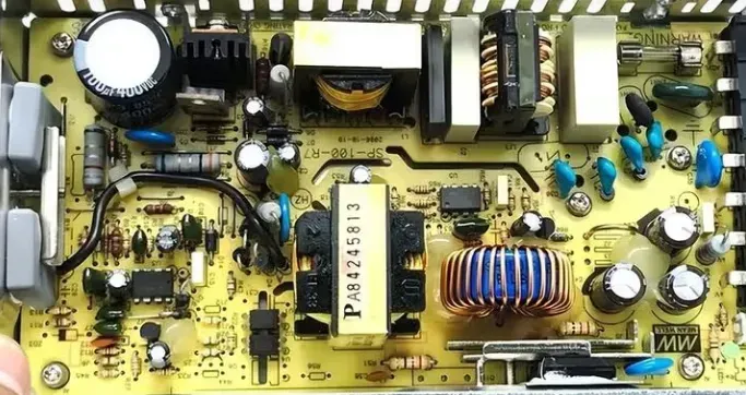
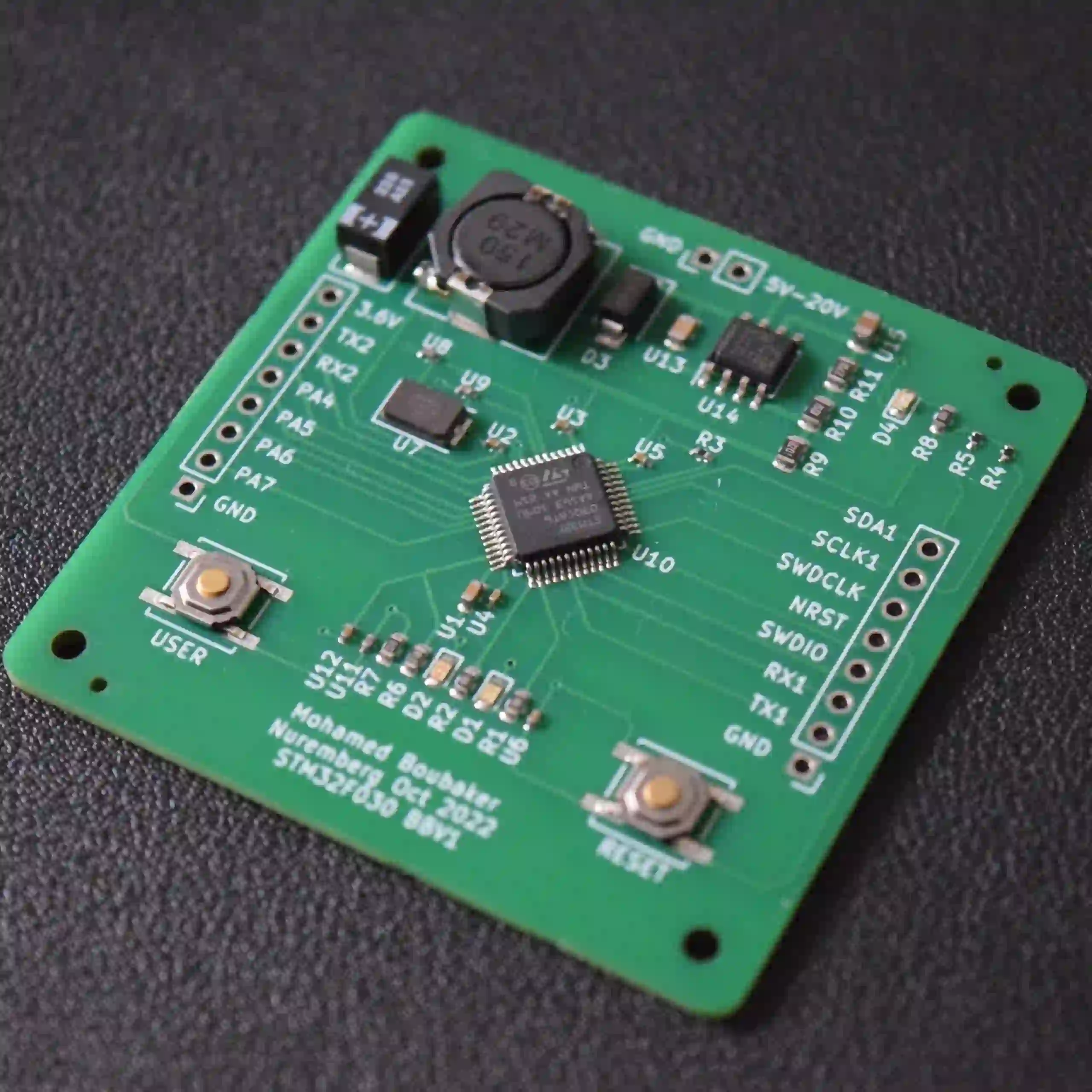
A switch-mode power supply (SMPS) is a high-frequency power conversion system that converts an input voltage at one level into regulated output voltages or currents at the levels required by downstream electronics. By rapidly switching energy through magnetic components, an SMPS achieves high efficiency, compact size, and flexible output configurations compared to linear supplies.
A typical AC-input SMPS processes power through the following stages: AC mains input → EMI filter → rectifier → power factor correction (PFC, active or passive) → primary-side switching stage (high-voltage side) that converts DC into high-frequency pulses → main transformer for isolation and energy transfer → secondary-side rectification → voltage regulation (e.g., magnetic amplifier or DC-DC conversion) → output filtering with inductors and capacitors to smooth ripple → supervisory and power-management circuitry.
The sections below walk through the common components at each stage, how they are used, and the engineering role each part plays in performance, reliability, and safety.
EMI Filtering at the AC Input
AC inlet and integrated EMI filters
The AC mains first enters the power supply through an inlet connector. Many supplies implement a two-stage EMI filter at the input to both attenuate interference arriving from the mains and suppress switching noise generated by the SMPS from being conducted back onto the mains. The EMI filter provides a low-pass function: it diverts or shunts high-frequency components to ground while allowing the 50/60 Hz fundamental to pass with minimal attenuation.
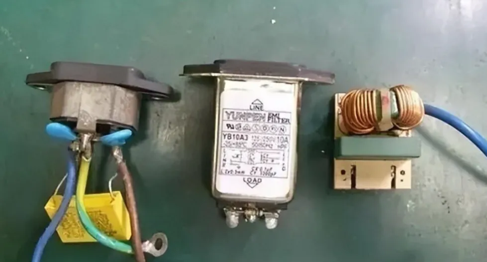
Some designs use an AC inlet module with an integrated EMI filter enclosed in a metal can to reduce noise leakage. Other designs place the EMI filter components on the main PCB. Mechanical constraints often determine which approach is used.
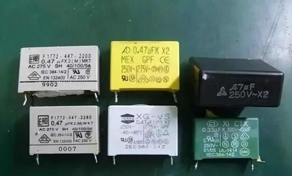
X capacitors (across-the-line safety capacitors)
X capacitors, typically marked “X” or “X2,” are connected across line (L) and neutral (N). They reduce differential-mode noise—noise that appears between L and N—by providing a low-impedance path for high-frequency components while presenting negligible effect at 50/60 Hz. These are safety-rated film capacitors designed to withstand mains transients.
Y capacitors (line-to-earth safety capacitors)
Y capacitors connect from each of L and N to protective earth (PE), chassis, or frame ground (FG). Their purpose is to attenuate common-mode noise—noise that is common to both L and N with respect to earth. Y capacitors are also safety-rated, designed to meet strict leakage and insulation requirements because they connect to accessible parts through the chassis.

In many power supplies, FG is bonded to the metal enclosure, PE, and the DC output return (0 V/GND). If PE is not connected, two Y capacitors from L and N to FG act as a capacitive divider, biasing the chassis to approximately half the mains potential (Vin/2) at high frequency. Touching the chassis in such conditions can produce a mild tingle due to small leakage currents within safety limits.
Common-mode choke
A common-mode choke is placed in series with L and N to suppress common-mode and high-frequency conducted emissions. Wound on a high-permeability core with both windings arranged so that normal 50/60 Hz differential currents cancel and common-mode noise adds, the choke presents a high impedance to common-mode noise while minimally impacting the mains current. Common-mode chokes can be toroidal or E-core types and often resemble small transformers with two coupled windings.
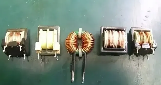
In summary, differential-mode noise (between L and N) is mainly shunted by X capacitors, while common-mode noise (from L/N to PE) is largely attenuated by the common-mode choke and Y capacitors. Together they help the supply meet EMI regulations and avoid interfering with other equipment.
Surge Protection and Front-End Rectification
Fuses and thermal fuses
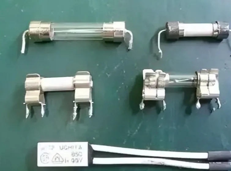
A fuse provides overcurrent protection at the input. When the current exceeds its rated value, the fuse opens to protect downstream circuitry. Cartridge fuses used in power supplies are commonly fast-acting and, for safety, may use a ceramic body filled with flame-retardant material to contain arcs at the moment of interruption. Thermal fuses, often attached to high-dissipation components such as cement resistors or heatsinks, open when a set temperature is exceeded, providing overtemperature protection. Thermal and current fuses may be used together for dual protection.
NTC inrush current limiter
At power-up, the primary bulk electrolytic capacitor is uncharged and can draw a large inrush current through the rectifier. An NTC (negative temperature coefficient) thermistor in series with L or N limits this surge: its cold resistance initially restricts the current, then as it self-heats under load its resistance drops to reduce power loss during steady-state operation. Disc-type NTCs are typically black or dark green.
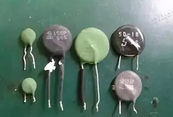
One limitation is that if the supply is toggled off and on quickly (“hot start”), the NTC may still be hot and exhibit low resistance, providing little inrush limiting. It also dissipates some power continuously. Modern high-efficiency designs increasingly adopt active inrush-control circuits or relay bypass schemes to minimize these drawbacks.
Metal-oxide varistor (MOV)
A metal-oxide varistor is connected across the mains (e.g., between L and N, or between L/N and PE depending on the design) to clamp surge voltages. Below its rated threshold the MOV is high impedance; above it, its resistance drops sharply and it conducts, diverting surge energy. This often causes the input fuse to open under severe surges, protecting downstream components. MOVs can fail open or short under extreme stress; visible damage can indicate surge events that warrant further inspection of the equipment.

Bridge rectifier
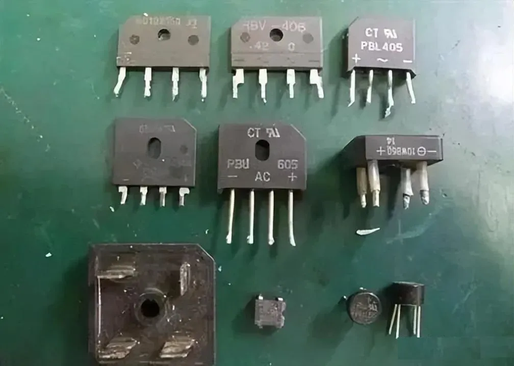
The bridge rectifier, built from four diodes in a full-wave configuration, converts the filtered AC into pulsating DC for the primary switching stage. Bridge modules vary in package and size according to voltage and current ratings; higher-power supplies often mount them to a heatsink to maintain reliability. The bridge feeds the primary bulk capacitor and the PFC/switching stage.
Primary Power Stage
Switching transistors
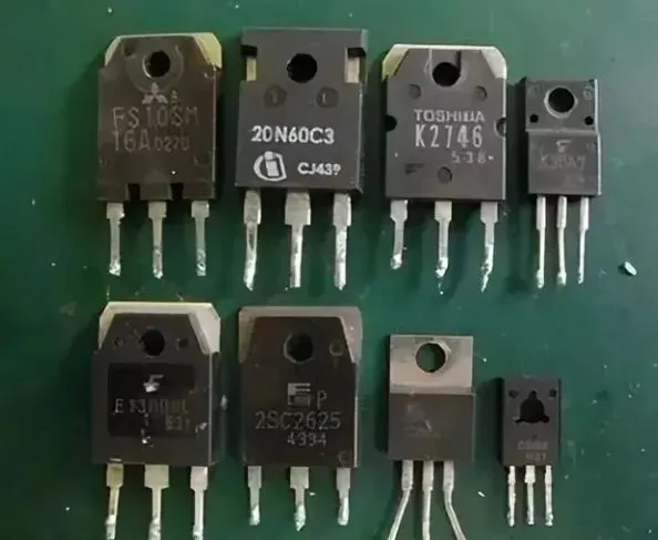
The primary switching devices, typically N-channel MOSFETs and sometimes NPN BJTs in certain topologies, act as high-speed, non-contact electronic switches controlled by PWM signals. They are critical in both the active PFC stage and the main primary converter. Depending on the chosen topology—forward, half-bridge, full-bridge, push-pull, etc.—device stresses, control method, and magnetic design differ, but the core function remains the same: rapidly commutate current to transfer energy through the transformer at high frequency. On the secondary side of high-efficiency supplies, MOSFETs may also be used for synchronous rectification to reduce losses compared to diode rectifiers.
Main transformer and isolation
The main transformer provides galvanic isolation between the high-voltage primary and low-voltage secondary while coupling energy via the magnetic field. Isolation eliminates shock hazards in fault conditions and allows the design to generate multiple output voltages easily by adding secondary windings. Because SMPS operate at tens to hundreds of kilohertz or higher, their transformers are much smaller than 50/60 Hz mains transformers for the same power level.
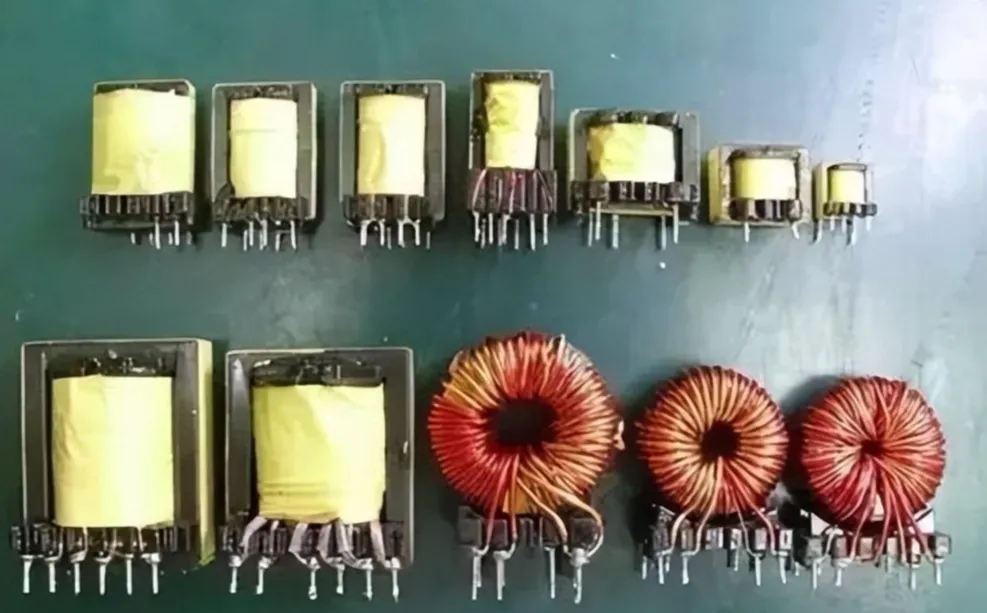
High-power supplies may use multiple transformers to distribute flux, prevent core saturation at high load, and optimize thermal performance. In addition to the main power transformer, small pulse transformers and saturable reactors may be present for signal coupling or magnetic amplifier post-regulation. After isolation, the secondary voltages are rectified, regulated, and filtered into stable DC rails for the system.
Secondary Power Stage and Output Filtering
Diodes
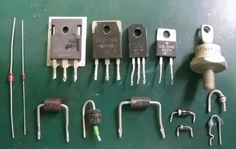
Power supplies use different diode types depending on circuit location and performance needs. Common devices include:
- Schottky barrier diodes (SBD): Low forward drop and fast switching, widely used for secondary rectification to reduce losses.
- Fast recovery diodes (FRD): Used where higher reverse voltage ratings and controlled recovery are needed, such as in active PFC and primary-side snubber/rectifier circuits.
- Zener diodes (ZD): Provide voltage references and clamping functions in control and protection circuits.
Inductors
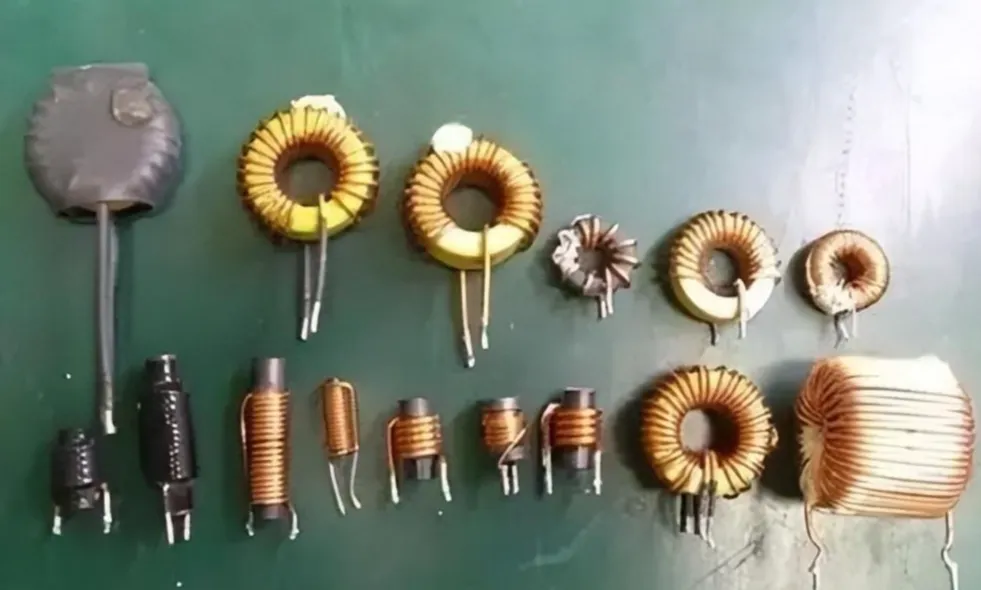
Inductors serve as energy storage elements and filters. Their roles include output choke filtering after secondary rectification, magnetic amplifier (mag-amp) regulation elements in some designs, and energy storage in DC-DC stages. Inductance value, core type, and wire gauge are selected for the required ripple current, saturation current, and thermal performance. Inductors may be toroidal or rod/cylindrical forms; turns count and conductor thickness scale with inductance and current ratings.
Electrolytic capacitors
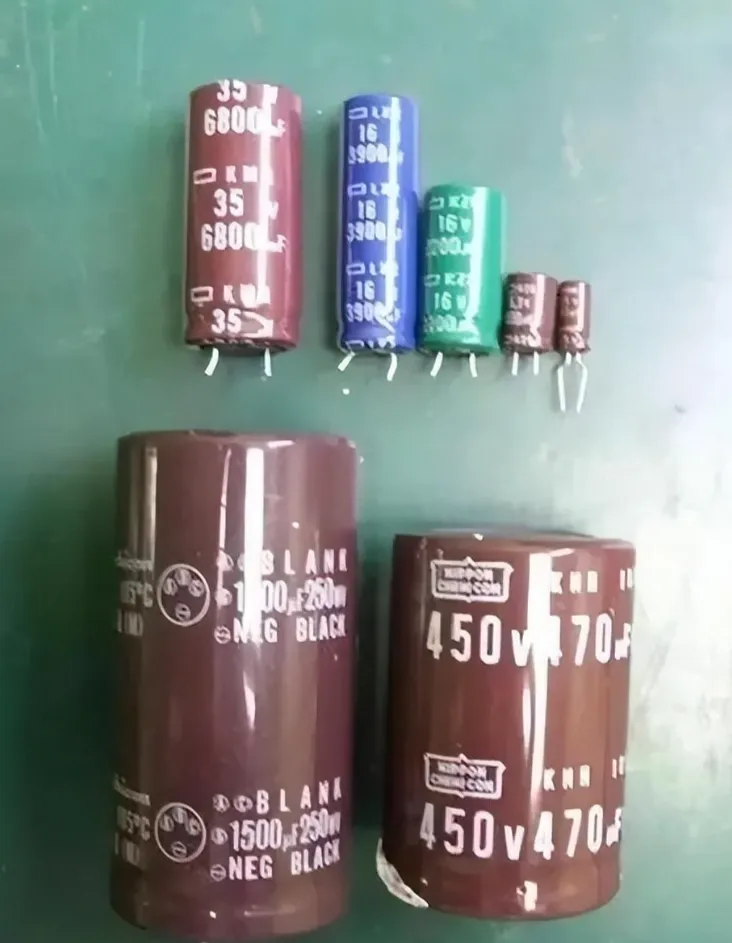
Capacitors complement inductors by storing energy and smoothing ripple. On the primary side, high-voltage bulk electrolytic capacitors hold the rectified mains for the primary converter or PFC stage. On the secondary side, multiple high-temperature, long-life, low-impedance electrolytics filter each output, minimizing ripple voltage and ESR-related heating during continuous charge/discharge cycles. The chemistry of electrolytic capacitors is sensitive to temperature; lifetime and reliability are strongly influenced by operating temperature, so both component selection and the supply's thermal design are critical to long-term stability.
Resistors
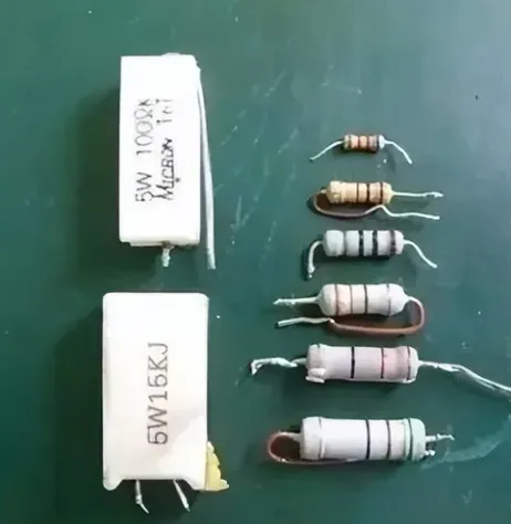
The SMD resistor can be used for many support functions: current limiting, voltage sensing, timing, snubbing, and as bleed resistors to safely discharge capacitors when the supply is switched off, reducing shock risk. Power resistors (e.g., cement types) handle large surges and dissipation, while standard film resistors indicate value and tolerance via color bands.
Control, Feedback, and Protection
Control ICs
Control ICs manage power conversion, regulation, and protection across the supply:
- PFC controller: Active PFC maintains a specified power factor and suppresses high-order harmonics drawn from the mains.
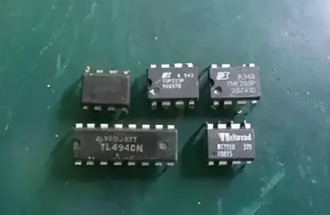
- Primary PWM controller: Generates the PWM drive for the primary switching devices and controls duty cycle to regulate output power. Well-known families include UC3842/3843 series, among others.
- Integrated PFC/PWM controller: Combines both functions in one IC to reduce component count and simplify design; examples include controllers similar to CM680X-class devices.
- Auxiliary supply controller: A low-power, independent offline switch controller powers standby functions and the control logic even when the main outputs are off. Integrated “off-line switcher” families such as TOPSwitch are commonly used for this purpose.
Supervisory and protection functions
Comprehensive protection is essential for safety and reliability. Typical supervisory ICs implement UVP (undervoltage protection), OVP (overvoltage protection), OCP (overcurrent protection), SCP (short-circuit protection), and OTP (overtemperature protection). When a fault threshold is exceeded, the controller shuts down and often latches off the supply until the fault is removed or power is recycled.
Optocoupler isolation feedback
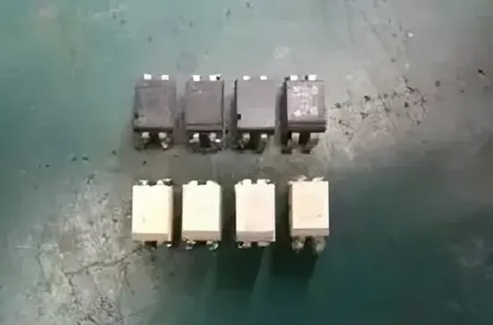
Optocouplers transfer control and feedback signals across the isolation boundary between primary and secondary. An LED on the secondary side drives a phototransistor on the primary side, allowing accurate regulation of the isolated outputs without a direct electrical connection. This preserves safety isolation while preventing fault currents from propagating between high- and low-voltage domains.
By understanding how each component contributes—filtering conducted emissions, limiting surges, converting and regulating power, and ensuring safe operation—engineers can diagnose issues, optimize designs for efficiency and EMI compliance, and improve reliability across the full operating life of the supply.