










Static flexible circuits are bent only once or a few times during assembly and then remain fixed for the entire product life. Dynamic flexible circuits bend repeatedly during normal operation such as in hinges sliding mechanisms or wearable devices. The core difference lies in mechanical duty cycle. Static designs mainly need to survive a single forming step without cracking while dynamic designs must resist copper fatigue over thousands or millions of cycles. In design the first and most important step is to correctly classify the application then choose matching bend radius copper type stack-up and layout rules so the circuit stays reliable without unnecessary cost.
Highlights
• Correct application classification as static or dynamic is the foundation of every reliable FPC design.
• Dynamic flex requires much larger bend radii and rolled-annealed copper while static flex allows tighter radii and electrodeposited copper.
• A practical design checklist plus strain-aware routing and real bend testing prevent most field failures.
In the sections that follow you will find clear definitions quantitative bend-radius guidelines drawn from IPC-2223 practice practical life-estimation methods construction recommendations a ready-to-use design checklist and real application lessons.
Static FPC vs Dynamic FPC: What's the Difference?
What Is Static FPC?
Static flex means the circuit is bent once or at most a handful of times during assembly or service and then stays fixed for the life of the product. Typical examples include a display interconnect folded into a sealed enclosure, a camera-module cable shaped once into a compact housing, or a rigid-flex transition that simply needs to conform to a chassis.
What Is Dynamic FPC?
Dynamic flex means the circuit experiences repeated bending, sliding, or rolling during normal operation. Laptop hinges, printer-head cables, wearable wristbands, robotic joints, and foldable-device mechanisms fall into this category. Cycle counts routinely range from tens of thousands to several million.

Difference between Static Flex vs Dynamic Flex
The mechanical difference is fundamental. Static loading is primarily a forming event: the copper must stretch or compress once without cracking or delaminating. Dynamic loading is cyclic fatigue. Every bend adds a small increment of plastic strain; over time the copper work-hardens, cracks initiate, and the circuit opens. Reliability expectations therefore diverge sharply. Static designs are judged by successful installation and long-term dimensional stability, while dynamic designs are judged by cycle life under the actual motion profile, temperature, and environment.
Hybrid cases exist, that is occasional service loops that may see a few dozen bends over a product lifetime. Treat anything above roughly 100 expected cycles as dynamic unless extensive testing proves otherwise. Misclassification is expensive: using static-grade materials and radii in a dynamic hinge produces field failures and warranty claims; using full dynamic construction for a pure static fold wastes material cost and board real estate.
Static vs Dynamic FPC: Bend Radius Requirements
Copper fatigue life is governed by the strain amplitude experienced by the foil. Strain is controlled mainly by the ratio of FPC bend radius to total flex thickness and by how far the copper sits from the neutral axis. IPC-2223 and industry practice therefore express minimum bend radius as a multiple of finished flex thickness (copper + dielectric + coverlay).

Typical guidelines used in production, for a detailed treatment of bend-radius calculation, see our guide to FPC minimum bend radius:
|
Application |
Layers in Flex Zone |
Minimum Bend Radius |
Notes |
|---|---|---|---|
|
Static (flex-to-install) |
1–2 |
6–10× |
ED or RA copper acceptable |
|
Static |
3+ |
12–20× |
Bonded layers increase required radius |
|
Dynamic |
1 |
100× |
RA copper strongly preferred; single-sided preferred |
|
Dynamic |
2 |
100–150× |
Keep copper near neutral axis; multilayer rarely used |
|
Dynamic |
3+ |
Generally not recommended |
Extremely large radii required if attempted |
These ratios work for standard polyimide boards that use half-ounce or thinner copper. If you use heavier copper, more layers, or adhesive systems, the board becomes stiffer and needs a larger bend radius. Always leave extra room. Most fabricators suggest making the radius 20 to 50 percent bigger than the calculated minimum when the product needs high reliability or will face high temperatures.
Bend angle and how often the circuit moves also affect life. A small gentle swing causes less damage than a full 180 degree fold and unfold. Bending in only one direction is easier on the copper than bending back and forth. The total number of cycles and the amount of strain matter more than the speed. But very fast motion can create local heat that shortens the life of the copper.
Material and Stack-up Choices for Static vs Dynamic FPC
RA vs ED Copper
When comparing RA vs ED copper, the primary difference lies in their grain structure and mechanical performance. Rolled-annealed (RA) copper possesses elongated horizontal grains, which provide it with superior ductility and significantly better resistance to cyclic fatigue compared to electrodeposited (ED) copper. ED copper's columnar grain structure makes it more brittle and prone to cracking under repeated strain. Therefore, RA copper is the superior choice for all dynamic applications and any static designs that might experience occasional service flex. For purely static flex-to-install parts, ED copper remains a more economical and acceptable alternative.
Single-Sided vs Double-Sided
Place copper as close as possible to the neutral axis in dynamic zones. A single-sided construction with coverlay on both sides naturally centers the foil. Double-sided designs should stagger traces so they do not stack on top of each other through the bend. Avoid solid copper planes; use hatched or meshed grounds to reduce stiffness.

Adhesive vs Adhesiveless
Adhesiveless laminates produce thinner, more flexible constructions and eliminate one potential delamination interface; they are preferred for high-cycle dynamic work. FPC adhesive systems are often adequate and lower-cost for static applications.
Coverlay and Stiffener
FPC coverlay is almost always preferred over flexible soldermask in bend regions because soldermask can crack after a modest number of cycles. Keep coverlay openings and transitions smooth; abrupt thickness changes create stress risers.
Stiffeners belong outside the bend zone. Transition regions between stiffener and free flex should be gradual. Use stepped coverlay or additional polyimide layers to avoid a hard edge that concentrates strain.
Trace routing
Trace routing inside the bend area should run perpendicular to the bend axis. Use gentle curves or teardrops at any width change. Never place vias, pads, or components in a dynamic bend zone; even static zones benefit from keeping plated holes well clear of the tightest radius.
Dynamic FPC Cycle Life and Strain
A practical first estimate begins with strain. Approximate maximum strain in a simple bend is distance from the neutral axis divided by the bend radius. For a centered copper layer the distance is roughly half the total thickness, so strain ≈ t/(2R). More precise calculations account for the actual neutral-axis location and the individual layer moduli.
Empirical fatigue curves for copper then relate strain amplitude to cycles-to-failure. Lower strain produces dramatically longer life—doubling the radius can increase cycle capability by an order of magnitude or more. Temperature, humidity, and chemical exposure reduce life further because they accelerate crack growth and adhesive degradation.

A simplified engineering workflow looks like this:
1. Determine required lifetime cycles and motion profile (angle, radius, direction, frequency).
2. Select a candidate stack-up and calculate strain at the copper.
3. Compare the strain to published or fabricator fatigue data for the chosen copper type.
4. Adjust radius, thickness, or copper placement until the predicted life exceeds the requirement with margin.
5. Validate with physical bend testing under representative environmental conditions.
Pure calculation is useful for ranking options but never replaces testing. Real constructions include manufacturing variations, residual stresses from lamination, and local stress concentrations that models miss. Always plan a qualification test that matches the product's stroke, speed, temperature range, and pass/fail criteria.
Design details that measurably improve calculated and actual life include wider traces in the bend zone and they will distribute current if a crack starts, generous fillets, continuous coverlay over the bend, and elimination of any abrupt geometry change.
Insights from Dynamic Bend Testing
Laboratory dynamic bend testing is the most direct way to measure how a flexible circuit will perform under repeated motion. In a typical setup the circuit is clamped in a fixture that forces it to bend back and forth around a fixed mandrel or through a controlled stroke that matches the product's actual movement. The test can run at room temperature or inside an environmental chamber that adds heat and humidity. Throughout the test the electrical resistance of the copper traces is monitored continuously. Failure is declared when resistance rises beyond a set limit or when an open circuit appears. Visual inspection after the test then reveals whether the copper cracked, the coverlay delaminated, or the adhesive layers separated.

Results from these tests show a clear performance gap. Constructions that follow the 100-times-thickness rule, use rolled-annealed copper, and keep the copper near the neutral axis routinely reach hundreds of thousands to several million cycles before resistance drifts. The same geometry built with electrodeposited copper or with a smaller radius often fails after only a few thousand cycles. Single-sided adhesiveless boards with RA copper consistently outlast double-sided adhesive-based builds of similar thickness. Staggered traces and hatched ground planes further reduce local stress and extend life. When a design fails early, the root cause is almost always an underestimated radius, copper placed too far from the neutral axis, or a via or pad left inside the flex zone.
A useful qualification test must therefore copy the product's real motion, include the expected temperature and humidity range, and continue long enough to prove the required lifetime with statistical confidence. Continuity checks performed only at the end of a fixed cycle count are not enough. Continuous resistance monitoring and a defined drift threshold give a far more accurate picture of performance.
Static vs Dynamic FPC Design Checklist
Use this checklist at the start of every flex circuit design and again during DFM review with the fabricator.
Application Classification
● Confirm static (<100 cycles expected) or dynamic (continuous or high-cycle).
● Document exact motion profile: radius, angle, direction, frequency, environment.
Mechanical Requirements
● Calculate minimum bend radius from thickness and duty cycle; add safety margin.
● Define free flex length and any service loops.
Stack-up and Materials
● Choose RA copper for dynamic; ED acceptable only for pure static.
● Prefer adhesiveless and single-sided construction in dynamic bend zones.
● Keep total thickness as low as electrical requirements allow.
● Place copper on or near neutral axis.
Layout Rules
● Route traces perpendicular to bend axis; use curves, never sharp corners.
● Keep vias, pads, and components out of the bend zone.
● Use teardrops and staggered traces where multiple layers are unavoidable.
● Design smooth stiffener-to-flex transitions.
Coverlay and Finishing
● Prefer polyimide coverlay over soldermask in flex regions.
● Control coverlay openings and registration.
Qualification
● Specify a bend test that matches product motion and environment.
● Review the complete design with the fabricator before tooling.
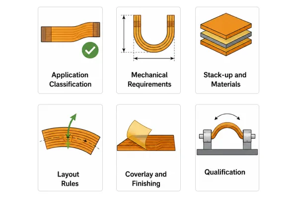
Items marked dynamic are mandatory for high-cycle applications and may be relaxed for pure static use. Joint DFM review catches most problems before they become expensive.
AIVON's Real Case: When Material Constraints Limit Cycle Life
One recent project with AIVON showed exactly how material limits can force a redesign of dynamic flex expectations.
A customer came to us with a wearable device cable that needed to survive 80,000 to 100,000 bend cycles. The mechanical drawing specified a tight radius and continuous motion. The bill of materials also required DuPont polyimide. During the early quotation review our engineers immediately saw a conflict. DuPont's available stock for that thickness was only double-sided copper. To meet the single-sided requirement we would have to etch away one entire copper layer. The customer also insisted on coverlay on both sides for protection and appearance.
Etching one side of a double-sided laminate leaves the remaining copper farther from the true neutral axis. Adding coverlay on both faces further increases total thickness and stiffness. Under repeated bending the copper would experience higher strain than a true single-sided adhesiveless construction. Our internal life data showed that this stack-up could reliably reach only about 15,000 to 20,000 cycles before resistance began to drift. Pushing for 80,000 to 100,000 cycles with the specified materials would almost certainly produce early field failures.
We presented the analysis to the customer with clear options. One path was to keep the DuPont material and the double-sided coverlay but lower the cycle target to 20,000 or less and enlarge the bend radius slightly. The second path was to switch to a true single-sided adhesiveless laminate from another qualified supplier that could support the original high-cycle target. The customer chose the first path because the DuPont brand was a hard requirement for the product family. We adjusted the stack-up drawing, increased the radius by a modest amount, and wrote a new qualification test based on 20,000 cycles. The boards passed the revised test with comfortable margin and the product launched without reliability issues.
When material brand or construction constraints conflict with the stated cycle life, the right response is not to force the original numbers. It is to quantify the real capability of the available stack-up and then reset either the life target or the materials so that both stay honest.
Manufacturing Considerations for Static and Dynamic FPCs
The FPC manufacturing process should reflect the intended mechanical behavior of the finished circuit.
For static FPCs, manufacturing attention typically focuses on dimensional accuracy, layer alignment, copper integrity, coverlay placement, and reliable connections.
For dynamic FPCs, additional attention should be given to the construction of the active flexing region, copper pattern, material selection, bend area, and mechanical consistency.
A manufacturer should understand the expected movement, bend radius, flexing direction, and application environment before finalizing the FPC stack-up.
Conclusion
Correct classification of static versus dynamic flex is the foundation of reliable FPC design. Static applications need only survive a single forming step and can therefore use tighter radii and electrodeposited copper, while dynamic applications must resist copper fatigue over thousands or millions of cycles and require larger radii, rolled-annealed copper, neutral-axis placement and the thinnest practical stack-up. Once the duty cycle is fixed, the highest-impact steps are applying the matching bend-radius and material rules, estimating life from strain then verifying it with realistic bend testing, and running every design through a structured checklist before release to fabrication. The same disciplined alignment of mechanical requirements, material capability and life targets also guides related decisions such as rigid-flex transitions and high-reliability environments, keeping both field failures and unnecessary cost under control.
FAQs
Q1: Can I use the same bend-radius rules for both static and dynamic FPCs if I simply add a safety factor?
A1: No. Dynamic applications introduce cyclic fatigue that static bend-radius rules do not address. Simply increasing the static bend radius is rarely sufficient; copper type, layer count, and neutral-axis placement must also be considered. Use the appropriate IPC-2223 design guidance for the intended flex class from the beginning.
Q2: How do temperature and humidity affect dynamic flex life estimates?
A2: Elevated temperature and humidity can accelerate copper crack growth and adhesive degradation. Dynamic flex life estimates based only on room-temperature strain data should therefore be derated for harsh environments. Many qualification programs include combined environmental exposure and mechanical cycling to validate actual service life.
Q3: When does it make sense to switch from pure FPC to rigid-flex for a dynamic application?
A3: Rigid-flex is a good choice when the dynamic section must remain thin and flexible while the rest of the circuit requires high component density or mechanical support. The flexible section can be optimized for repeated motion, while the rigid sections provide stable mounting areas for connectors and heavier components.
Q4: Are there cases where a static-grade FPC can survive limited dynamic motion?
A4: Yes. Occasional service flex may be tolerated with conservative bend radii and RA copper, but the design should be validated through life testing that reproduces the expected service motion. This approach should not be relied on for continuous or high-cycle dynamic applications.
Q5: Can a static FPC be used in a dynamic application?
A5: A static FPC should not automatically be used for an application involving repeated movement. If the circuit will flex continuously during normal operation, its construction, bend radius, copper design, and materials should be evaluated for dynamic use.
Q6: Does a smaller bend radius make an FPC more flexible?
A6: Not necessarily. A smaller bend radius means the circuit is bent more tightly, which can increase mechanical strain on the copper and dielectric layers. The allowable bend radius depends on the FPC construction and whether the application is static or dynamic.
Q7: Can an FPC bend in different directions during operation?
A7: It can, but multidirectional movement requires additional mechanical evaluation. Changes in bending direction can affect the strain experienced by the circuit, particularly in applications with repeated movement.
Q8: What happens if an FPC is repeatedly bent beyond its design limit?
A8: Repeated bending beyond the intended mechanical limits can cause fatigue in the conductive and insulating layers. Over time, this may result in cracking, delamination, or intermittent and eventual electrical failure.
Q9: How should an FPC be tested for repeated bending?
A9: Dynamic FPC testing should reproduce the actual movement conditions as closely as possible, including bend radius, bending direction, movement speed, number of cycles, and environmental conditions. The acceptance criteria should be defined according to the application's reliability requirements.
Q10: Does FPC layer count affect dynamic bending performance?
A10: Yes. Increasing the number of layers generally changes the thickness and stiffness of the flex area, which can affect its bending behavior. For dynamic applications, the layer structure should therefore be considered together with copper thickness, dielectric materials, and the required bend radius.
Q11: Can components be placed on a dynamic FPC?
A11: Components can be included on an FPC, but components and other rigid features should generally be kept away from areas that undergo repeated bending. The component placement should be coordinated with the mechanical movement and active flexing zone.






