










In power electronics, DC-DC converters transfer DC energy between voltage levels. The switch node signal, commonly called the SW signal, controls the converter's switching element and directly affects conversion efficiency and stability. This article summarizes practical methods to verify SW signal integrity and identify potential issues.
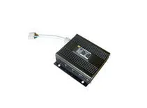
1. Why the SW Signal Matters
The SW signal drives the converter's switching device, typically a MOSFET. Its timing, rise and fall characteristics, and duty cycle determine switching losses, output regulation behavior, and electromagnetic emissions. Verifying the SW signal against design specifications helps ensure reliable operation under real conditions.
2. Common Test Methods
2.1 Oscilloscope Observation
Probing the switch node with a high-bandwidth oscilloscope is the most direct method. Inspect waveform shape, rise and fall times, overshoot, ringing, and duty cycle. Use a suitable probe grounding technique and bandwidth to avoid measurement artifacts. Compare measured parameters with design targets to detect anomalies.
2.2 Spectrum Analysis
A spectrum analyzer reveals the SW signal behavior in the frequency domain. It helps identify harmonics, switching noise, and unexpected spectral components that can affect EMI performance. Spectrum analysis also confirms the switching frequency and its stability under different conditions.
2.3 Load Response Testing
DC-DC converters operate under varying load conditions. Apply step changes or dynamic load profiles and observe how the SW signal and output respond. This evaluates control loop stability, transient response, and whether switching timing adapts correctly to load changes.
3. Advanced Test Techniques
3.1 Time-Domain Reflectometry (TDR)
TDR can detect impedance mismatches and faults at the switch node by analyzing reflected waveforms. It is useful for locating layout-related issues or discontinuities in the switch path. TDR requires specialized equipment and careful interpretation.
3.2 Crosstalk and System-Level Interference Tests
At the system level, assess how nearby signals and PCB layout affect the SW node. Inject or simulate adjacent switching activity and measure induced disturbances. Crosstalk testing helps validate isolation, routing, and decoupling strategies to maintain stable operation in complex environments.
4. Conclusion
Verifying the SW signal is a critical step in DC-DC converter design and validation. A combined approach using oscilloscope observation, spectrum analysis, load response testing, and advanced techniques such as TDR and crosstalk testing improves the likelihood of detecting issues early. Prioritizing thorough SW signal testing during development and production helps ensure converters perform reliably across operating conditions.






