This article evaluates the conversion efficiency of a classic "Joule thief" LED driver built around a high-frequency autotransformer (a self-oscillating blocking oscillator). The question is simple: of the electrical energy drawn from the source, how much ends up as electrical power delivered to the LED?
Introduction
The Joule thief is popular for its ability to light an LED from a "dead" 1.5 V cell. It achieves this through a simple self-oscillating boost action using a bifilar-wound inductor and a bipolar transistor. However, the circuit trades simplicity for performance. To quantify that trade-off, this work measures the electrical conversion efficiency of a specific Joule thief LED driver using practical shunt measurements at several supply voltages.
Conversion efficiency is defined here as the ratio of average electrical power delivered to the LED to the average electrical input power from the source. Optical output is not measured; the focus is purely electrical.
Circuit Under Test and Measurement Method
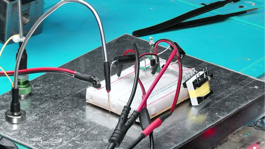
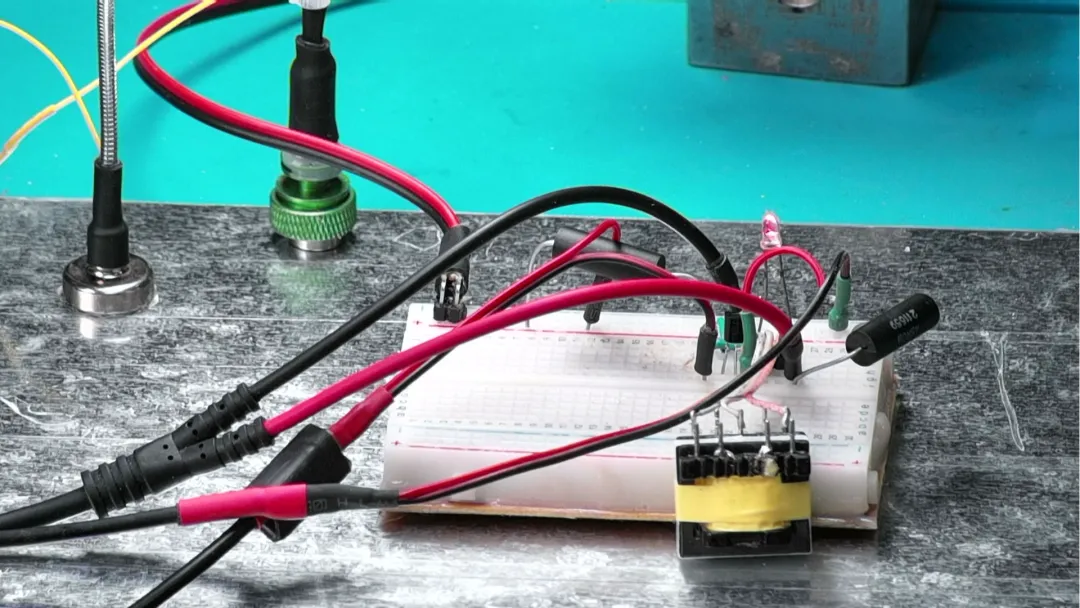
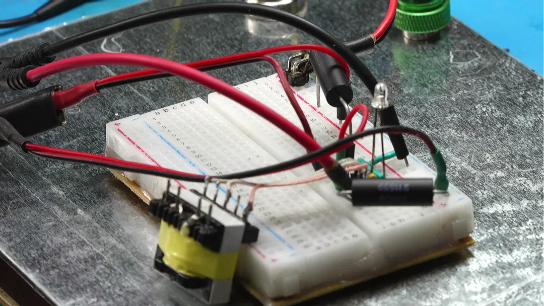
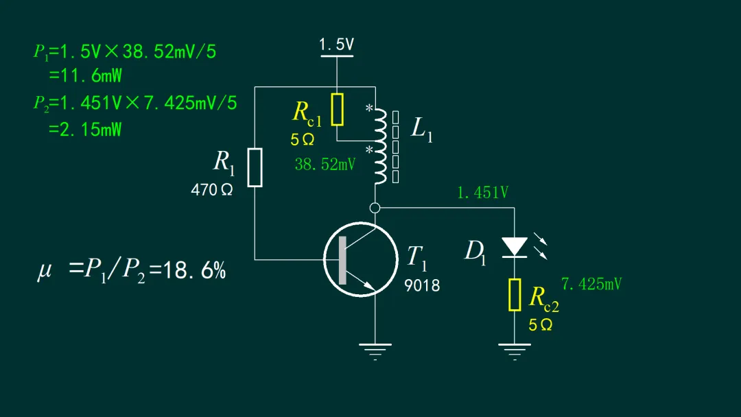
The circuit under test is a Joule thief based on a high-frequency autotransformer and a discrete NPN transistor. To measure input power and LED power, two 5 Ω current-sense resistors are inserted: one in series with the input supply and the other in series with the LED. Average voltages across the shunts are measured with a digital multimeter. Multiplying the average shunt voltage by 1/5 Ω yields the average current. Average input power is computed from supply voltage times input current. Average LED electrical power is computed from LED current times the LED's average forward voltage.
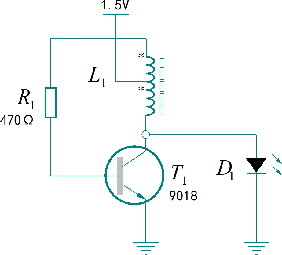
Figure 1.1.1 | Experimental schematic

As an example, at a nominal 1.5 V supply the following measurements were recorded:
- Supply voltage: 1.451 V
- Input shunt voltage: 38.52 mV across 5 Ω ? average input current ≈ 7.70 mA
- LED shunt voltage: 7.425 mV across 5 Ω ? average LED current ≈ 1.485 mA
From these values, the input electrical power is approximately 11.5 mW. The LED electrical power is approximately 2.15 mW. The corresponding conversion efficiency is therefore under one-fifth (about 19%). In other words, most of the energy drawn from the source is consumed by the driver itself rather than delivered to the LED.
Efficiency Across Input Voltage
To observe how efficiency varies with input voltage, the supply was swept from 0.6 V to 2.0 V using a bench source (DH1766). For each operating point, average input current, LED current, and LED forward voltage were measured using the same 5 Ω shunt method. One hundred samples were taken per point to compute average input power, average LED power, and the corresponding conversion efficiency.
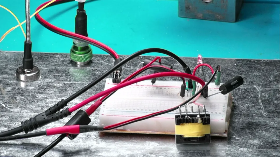
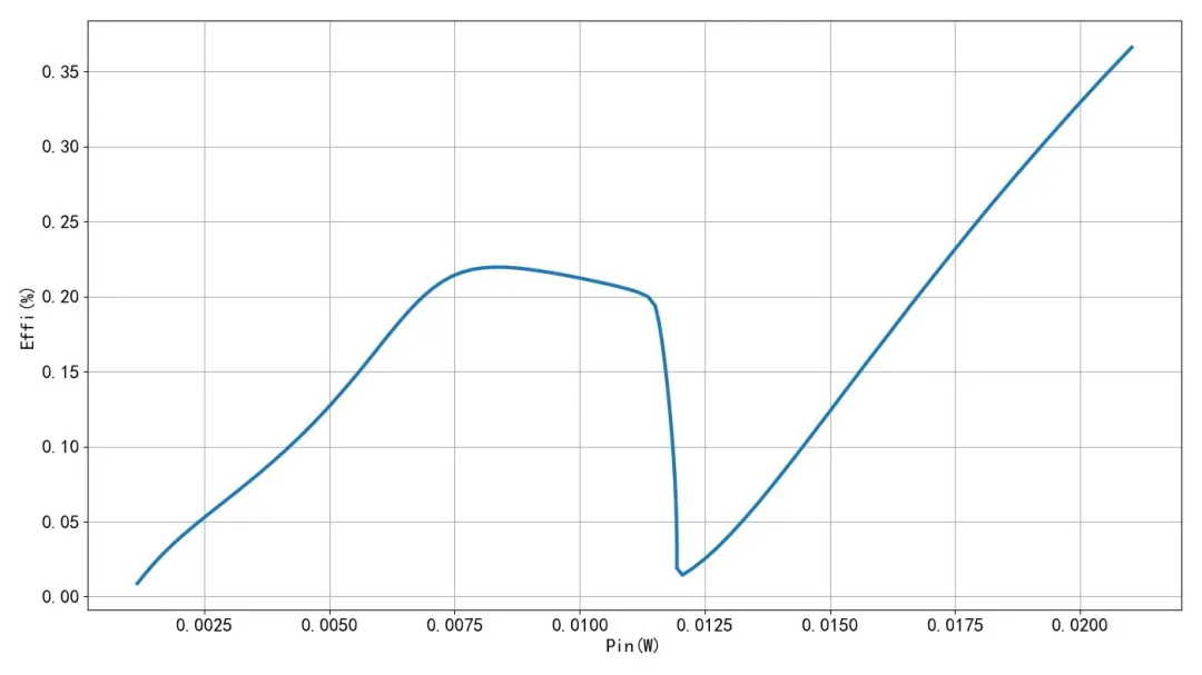
Figure 1.2.1 | Efficiency versus input power
The efficiency curve shows two distinct operating regions around approximately 1.7 V. Above about 1.7 V, the LED could be driven directly by the supply without any boost action, yet the Joule thief continues to oscillate, incurring switching and magnetics losses. In this region, the measured conversion efficiency is very low, on the order of ~3%. As the voltage increases further, efficiency improves but remains poor because the conversion stage is unnecessary for a forward-biased LED at these voltages.
Below this threshold, in the 1.1–1.5 V region, the Joule thief provides the required boost to light the LED. Efficiency shows a slight improvement but peaks at below ~23% in this measurement set. As input voltage drops toward the low end of the sweep, the circuit's oscillation conditions degrade, losses grow relative to delivered load power, and the efficiency falls until oscillation ceases.
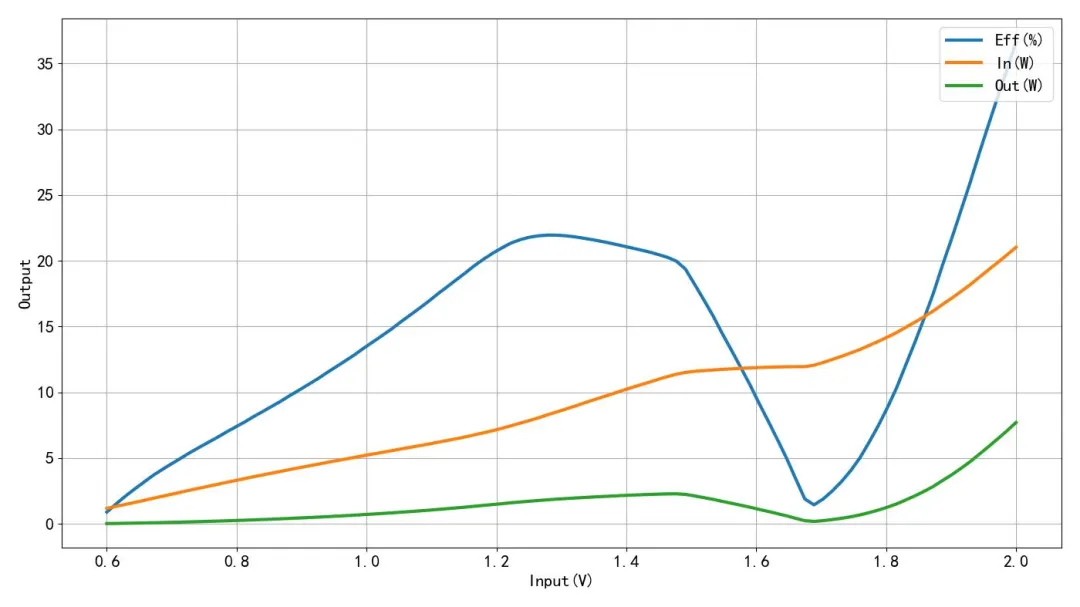
Figure 1.2.2 | Input and output power versus supply voltage
Why Is the Efficiency So Low?
A Joule thief is a minimalist, self-oscillating boost topology. Its simplicity makes it easy to build but also limits conversion efficiency. Several mechanisms contribute to the low values measured here:
- Magnetizing current and core losses: The autotransformer's magnetizing current sets up the oscillation. Energy is stored and released each cycle, but not all of it is transferred to the load. Core hysteresis and eddy-current losses dissipate a portion of the stored energy every cycle, especially as frequency rises.
- Copper losses: The DC resistance of the windings dissipates power proportional to I2R. The winding resistance is often significant for small hand-wound toroids or ferrite beads commonly used in Joule thief builds.
- Transistor conduction and switching losses: The NPN transistor alternately saturates and cuts off. When saturated, VCE(sat) dissipates power in proportion to collector current. During transitions, switching losses occur because both voltage and current are nonzero simultaneously. Base drive current also contributes to loss; without a controlled drive scheme, base bias can be excessive or poorly timed.
- Leakage inductance and ringing: Imperfect coupling between windings results in leakage inductance. When the transistor turns off, leakage energy can cause ringing and be dissipated in parasitic resistances instead of transferring to the LED.
- Load mismatch: The LED is a nonlinear, voltage-dependent load. The Joule thief delivers pulsed current with a duty cycle determined by the magnetic and transistor dynamics, which may not coincide with the LED's most efficient operating point. At higher input voltages where the LED is already forward-biased, forcing oscillation adds overhead without benefiting the load.
- Measurement shunt impact: Although small (5 Ω), the series sense resistors introduce additional loss and slightly alter the operating point, marginally lowering the measured efficiency. This effect is minor compared with the fundamental loss mechanisms above.
How the Joule Thief Operates
The circuit is a blocking oscillator. When power is applied, a small base current turns the transistor on, causing current to ramp in the transformer's primary. By transformer action, the feedback winding drives the base harder, accelerating the rise. As magnetizing current increases, the core approaches saturation and the rate of change of flux decreases. The feedback collapses, the transistor turns off, and the stored magnetic energy is released into the load via the secondary action, creating a boosted voltage sufficient to forward-bias the LED. After energy is delivered, the core resets and the cycle repeats. The oscillation frequency and duty cycle depend on the core, winding turns, transistor characteristics, and load.
This mechanism is inherently open-loop and bang-bang in nature. Without regulation, the operating point drifts with supply voltage, temperature, and component tolerances. That variability often pushes the circuit away from optimal energy transfer, which is why practical efficiency tends to be low and inconsistent across operating conditions.
Measurement Considerations
Because the Joule thief is a pulsed system, instantaneous currents and voltages are nonsinusoidal. Using a digital multimeter to read average voltages across sense resistors provides the correct average currents for calculating average power, provided the meter's bandwidth and sampling properly average over many cycles. However, a couple of subtleties are worth noting:
- LED voltage waveform: The LED forward voltage is time-varying during the pulses. Using a single DC reading may not capture peaks and ripple. A better method is to measure the LED voltage waveform with an oscilloscope and compute the time average over multiple cycles.
- Sense resistor placement and parasitics: The sense resistors should be placed to minimize loop inductance, and their tolerance and temperature coefficient should be known. In very low-voltage systems, even tens of millivolts of drop alter the operating point.
- Sampling: Averaging multiple readings at each operating point, as done here (100 samples), helps reduce random measurement noise and provides more stable average values.
Design Notes to Improve Efficiency
While a Joule thief is rarely competitive with modern regulated boost converters, several practical steps can improve its performance if this topology must be used:
- Core material and winding: Use a low-loss ferrite core suitable for the intended frequency range. Keep winding resistance low by using appropriate wire gauge and minimizing unnecessary turns. Good coupling between windings reduces leakage and ringing losses.
- Turns ratio optimization: Adjust the turns ratio to achieve the target LED forward voltage under load without excessive peak currents or overdrive. Too few turns increase current and core loss; too many turns increase copper loss and limit current ramp.
- Transistor selection and drive: Choose a transistor with low VCE(sat), adequate gain at the operating current, and fast switching. Add or optimize base resistors to limit unnecessary base current and shape the switching behavior. A small capacitor across the base network can help with turn-off characteristics if needed.
- Clamp and rectification: If a DC output is preferred, route the flyback energy through a Schottky diode into a small reservoir capacitor, then drive the LED from the rectified node. This can reduce LED current ripple and improve transfer of stored energy compared with direct LED conduction on pulses.
- Avoid unnecessary oscillation: At input voltages where the LED can be lit directly, bypass the oscillator or disable it to prevent needless switching losses. The Joule thief only adds value when it is genuinely boosting.
- Operate away from saturation: Driving the core deeply into saturation wastes energy. Tuning the feedback and turns to limit peak flux density can reduce core loss and improve repeatability.
Even with these optimizations, the Joule thief remains an open-loop switcher with limited efficiency. When battery life or energy efficiency matters, a dedicated boost regulator with proper control and synchronous rectification is typically the better choice.
Conclusion
The measured Joule thief LED driver delivers only a small fraction of its input power to the LED across the tested supply range. At 1.5 V, the circuit achieved roughly 19% conversion efficiency; at higher voltages where the LED could be driven directly, the efficiency dropped to only a few percent because the oscillator's losses dominated. In the lower-voltage region, efficiency peaked below approximately 23% before falling as the circuit approached its stop point.
These results underscore the inherent trade-offs of the Joule thief: it is simple and can light an LED from a low-voltage source, but it does so inefficiently. For applications where energy efficiency, predictable performance, and battery life are important, a regulated boost converter is the more suitable solution.