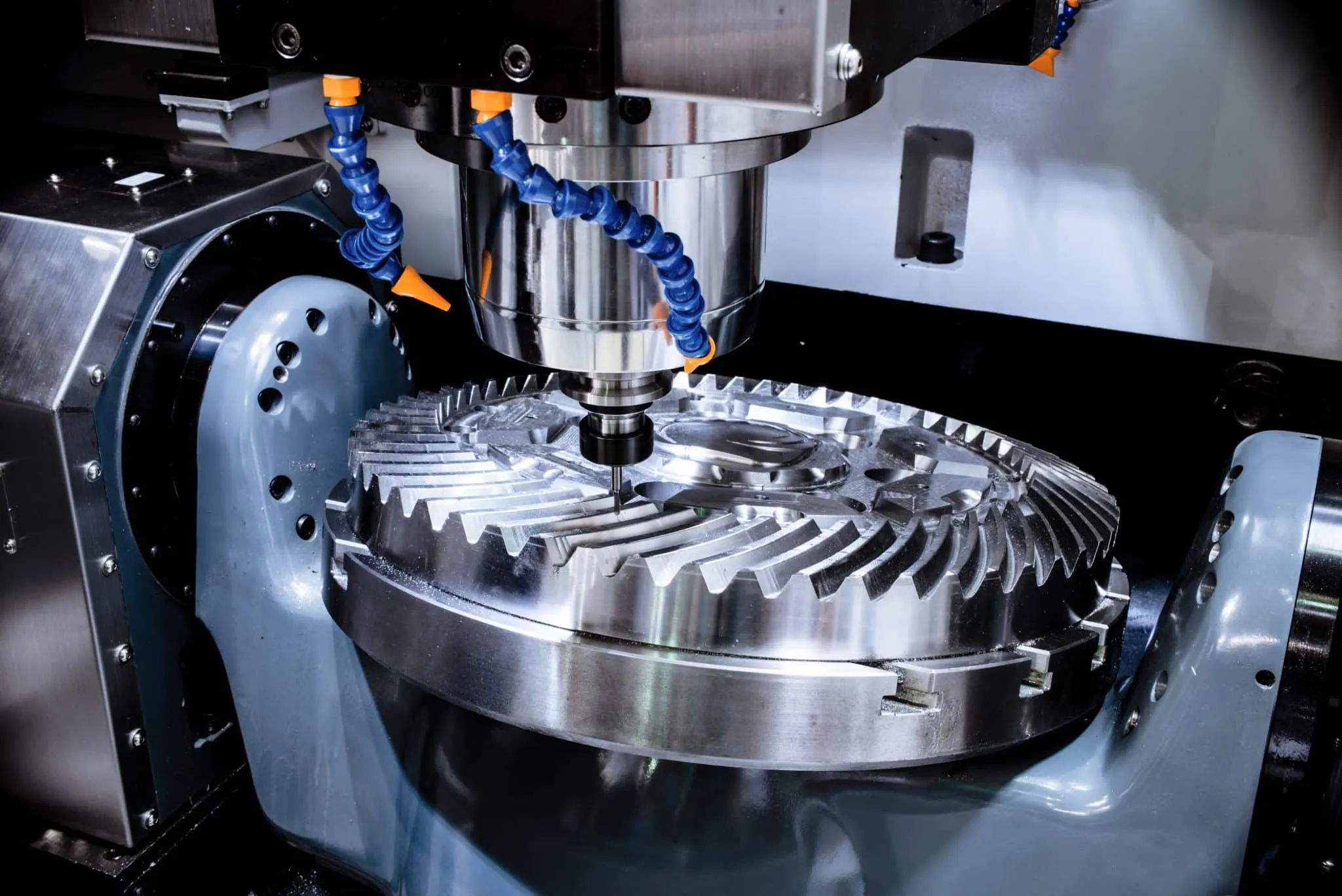
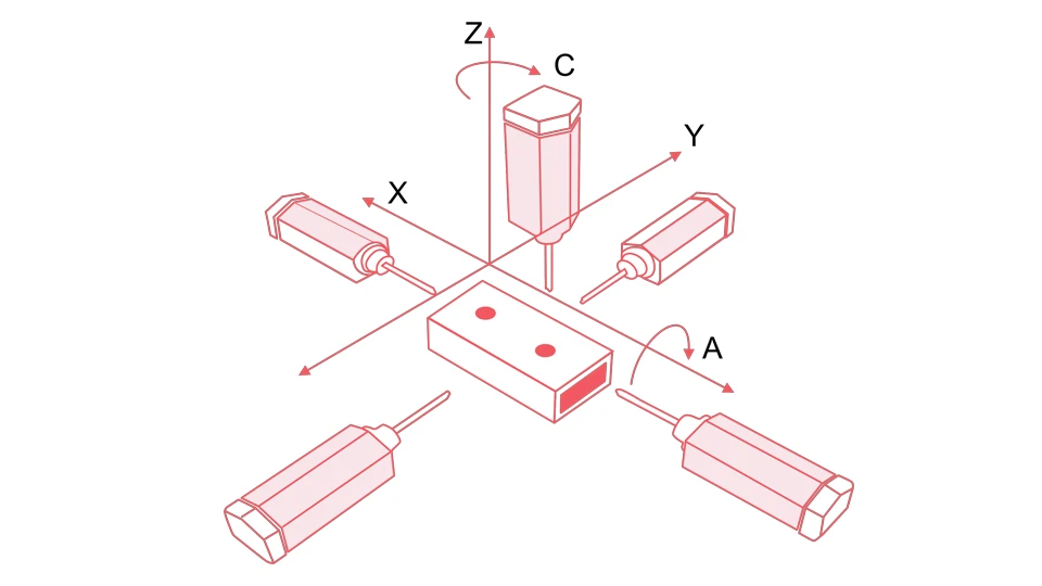
In production we treat CNC machining applications as the default route whenever a part needs true three-dimensional geometry, tight positional accuracy across multiple faces, or material that cannot be stamped or molded without secondary operations. CAM engineers load the solid model, generate tool paths with cutter compensation already baked in, and run the first article on a 3- or 5-axis machine before the rest of the panel or batch is released. That is the practical rule: if the feature cannot be produced by drilling, routing or etching alone, it goes to CNC.
Where the process window forces CNC instead of sheet-metal or molding
Sheet-metal brakes and progressive dies reach their limit once wall thickness drops below 0.8 mm or once internal pockets appear that cannot be formed without spring-back. Injection molds become uneconomical under a few hundred pieces and cannot hold the ±0.02 mm true-position tolerances common on connector interfaces. From the fabrication floor this shows up as scrap rates climbing above 8 % when those features are forced into the wrong process. CNC simply removes the material that other methods cannot reach, so the same aluminum 6061 or stainless 316 billet that would warp in a press stays within print.
Material behavior drives the same decision. Heat-treatable alloys used for aerospace brackets soften under the heat of welding or casting; medical-grade titanium oxidizes if left too long in a furnace. CNC keeps the part cold enough that the microstructure stays as-received, which is why most shops keep a separate cell for titanium and Inconel work.
What actually fails when the wrong process is chosen
Ignore the geometry and you see it on the first-article inspection report: hole positions drift 0.05 mm after anodizing because the stamping residual stress relieved, or a heat-sink fin array comes out with 0.1 mm wall-thickness variation that kills thermal performance. In electronics assemblies the housing no longer seats on the PCB datum pins; the assembly line stops while the fixture is reworked. Medical housings that should pass biocompatibility fail particle tests because secondary grinding left burrs. Aerospace brackets that were supposed to be CNC'd but were cast instead show porosity under X-ray and get quarantined. Shipment dates slip by two weeks while the batch is either reworked or scrapped.

How the shop floor actually executes the common applications
Electronics housings and RF shields are almost always 6061-T6 or 5052 plate. We fixture on the largest flat face, rough with a 12 mm end mill at 0.3 mm radial depth of cut, then finish with a 6 mm tool leaving 0.05 mm stock for a final spring-pass. Heat-sink fin arrays use a long-reach carbide mill with high-pressure coolant so chips evacuate; wall thickness is held to ±0.03 mm by measuring every fifth part with a height gauge. Brackets that mount to PCB stiffeners get all critical holes drilled after the outer profile is finished so that any residual stress does not shift the hole pattern.
Medical device enclosures and surgical-tool components run on machines that have been wiped down and validated for particulate. We switch to single-use coolant and change tools more frequently; surface finish is Ra 0.8 µm or better before passivation. Aerospace structural brackets and engine mounts are cut from billet rather than plate so grain direction can be controlled; 5-axis continuous tool paths keep the tool normal to the surface and eliminate the need for secondary hand blending. Automotive fixtures and check gauges are usually cut from tool steel or hard-anodized aluminum; the same CAM program that cuts the fixture also generates the inspection report template so the CMM program matches the machining datums exactly.
Compensation rules are simple and consistent across these CNC machining applications. Cutter diameter wear is measured every 20 parts and offset in the control; thermal growth of the spindle is compensated by a look-up table based on run time. For thin-wall housings we leave 0.15 mm extra stock on the first pass and take a light finishing cut after the part has cooled for 30 minutes. That sequence keeps dimensional yield above 97 % on most production lots.

When the strict CNC route can be relaxed
If the annual volume exceeds a few thousand pieces and the geometry is essentially prismatic, we move the part to a progressive die or investment casting with a CNC finishing station only on the critical faces. Prototype and bridge quantities stay on the mill regardless of volume because the setup cost is already sunk and the lead time is measured in days rather than weeks. Soft aluminum prototypes can sometimes be run on a router with a vacuum table if the tolerance stack is looser than ±0.1 mm; anything tighter or any stainless or titanium stays on the machining center. The trade-off is always the same: lower unit cost versus the risk of residual stress or surface defects that show up only after anodizing or passivation.
In short, the decision tree on the production floor is driven by geometry, material, and the next process the part will see. When those three factors align with what a CNC cell can deliver cleanly, that is the route we take.