From a fabrication standpoint, the decision between CNC milling vs CNC turning is rarely about which process is "better." It is about which process removes material more efficiently for the geometry you actually need to produce. When the part is primarily rotationally symmetric—shafts, bushings, flanges, or any feature that can be generated by rotating the workpiece against a stationary tool—turning usually wins on cost, cycle time, and process stability. When the part has prismatic features, pockets, slots, 3D contours, or non-cylindrical surfaces that require a rotating multi-point cutter, milling is the only practical choice. Mixing the two on the same workpiece is common, but forcing a pure turning job onto a mill or a pure prismatic job onto a lathe almost always increases cost and risk.
Where Each Process Wins in Real Production
In most machine shops the rule is simple: if the dominant features can be produced by spinning the stock and feeding a single-point tool, start with CNC turning. If the geometry demands multiple axes of tool motion relative to a fixed or slowly moving workpiece, start with CNC milling. Hybrid parts often go to a mill-turn center, but that is a capacity and tooling decision, not a default. The comparison below reflects what we see on the shop floor every day when quoting and processing both families of work.
| Dimension | CNC Milling | CNC Turning |
|---|---|---|
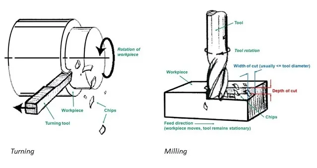
| Primary motion | Rotating multi-point cutter, workpiece fixed or indexed | Rotating workpiece, single-point tool |
| Best geometry | Prismatic, pockets, 3D surfaces, non-round | Cylindrical, conical, faces, grooves on axis of rotation |
| Setup complexity | Higher (fixturing, multiple ops, tool changes) | Lower for pure rotational parts |
| Typical cycle time | Longer for equivalent material removal on round parts | Shorter on rotationally symmetric parts |
| Tooling cost | Higher variety of end mills, inserts, holders | Lower—standard turning inserts dominate |
| Surface finish potential | Good, but tool marks more complex | Excellent on OD/ID when speeds/feeds are right |
| Material utilization | Often lower (more stock needed for clamping) | Higher on bar-fed or near-net stock |
| Mass-production suitability | Strong with pallet systems or multiple fixtures | Excellent with bar feeders and automatic loaders |
Quick Decision Matrix by Priority
| If your priority is… | Better Choice | Why |
|---|---|---|
| Lowest cost per part on round geometry | CNC Turning | Fewer setups, cheaper tooling, continuous cutting |
| Complex prismatic or 3D features | CNC Milling | Only practical way to generate non-rotational surfaces |
| Fast prototype of a shaft or bushing | CNC Turning | Simple program, standard inserts, quick changeover |
| Tight concentricity and roundness | CNC Turning | Workpiece rotation naturally generates true cylinders |
| High-volume bar stock parts | CNC Turning | Bar feeders + live tooling still beat milling for most round work |
| Deep pockets or thin-wall rectangular parts | CNC Milling | Turning cannot access internal prismatic features |
How Material Removal Actually Differs on the Machine
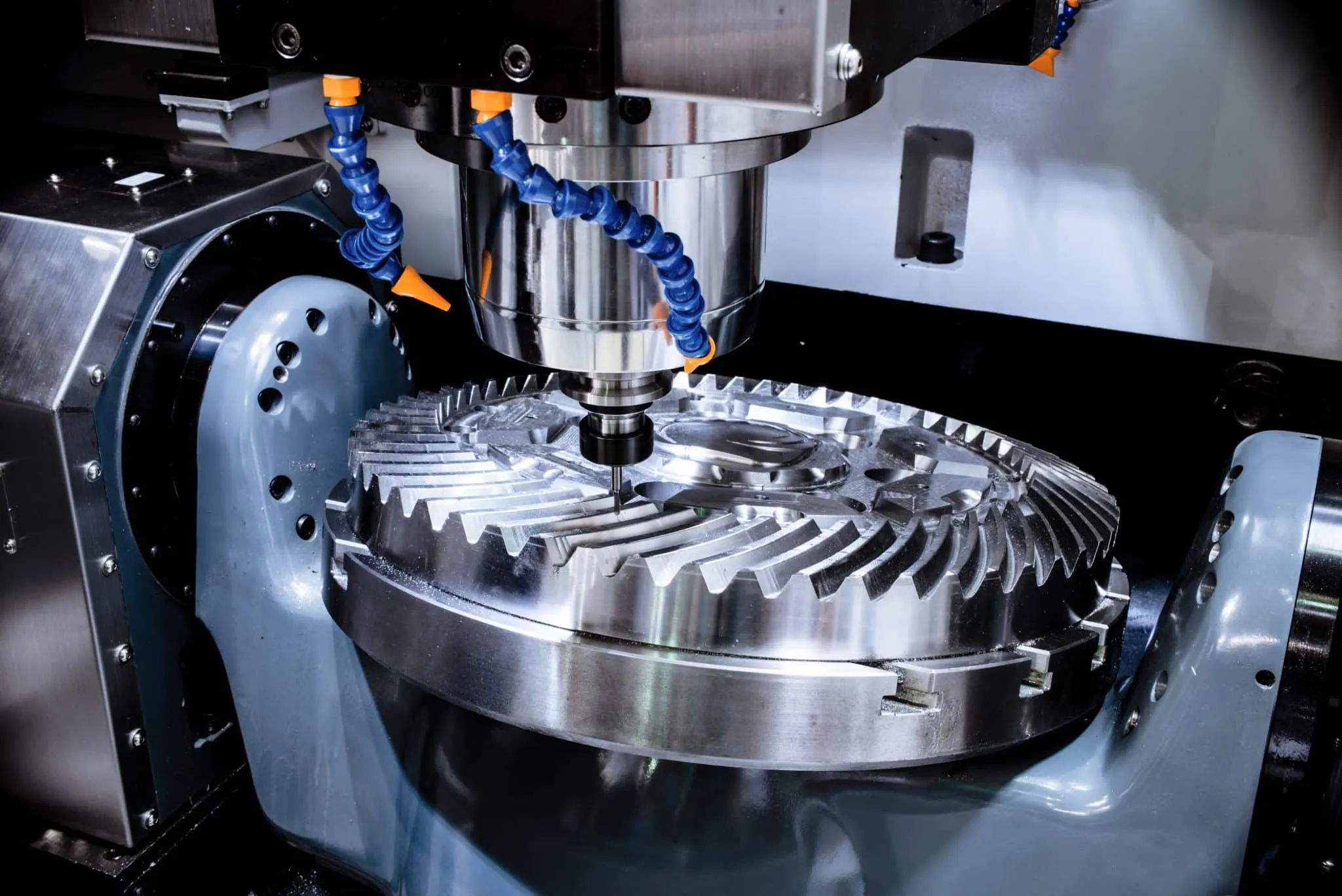
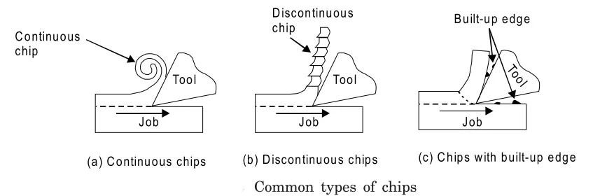
In CNC turning the workpiece spins at high RPM while a single-point insert is fed along or across the axis of rotation. Almost all cutting energy goes into continuous chip formation along a predictable path. That continuity is why turning can remove large volumes of material quickly and leave a uniform surface when the insert geometry and feeds are correct. CNC milling reverses the roles: the multi-flute cutter spins and the workpiece (or table) moves under it. Each tooth engages and leaves a discrete chip, so the process is inherently interrupted. Interrupted cutting generates more vibration, more heat cycles on the cutting edge, and more complex tool-path programming. From a process-stability viewpoint, continuous cutting on a lathe is simply more forgiving for the same volume of metal removed on a rotational part.
When the geometry forces interrupted cuts anyway—keyways, flats, or off-axis holes—milling becomes necessary and the lathe's advantage disappears. Trying to generate those features with live tooling on a lathe is possible but usually slower and more expensive than a proper milling operation.
Which Parts Naturally Belong to Each Process
Rotationally symmetric parts—shafts, pins, rollers, valve bodies, hydraulic fittings—belong on the lathe first. Even when secondary milling is required (cross holes, flats, keyways), the majority of the stock removal and the critical diameters are still done by turning. Non-rotational or highly prismatic parts—housings, brackets, mold bases, aerospace structural fittings—belong on the mill. Attempting to turn a rectangular block into a complex housing wastes material, time, and money. The decision is driven by the dominant geometry, not by the presence of a few cylindrical features. A part that is 80 % cylindrical and 20 % milled features is almost always cheaper and more accurate when the cylindrical work is done on a lathe (or mill-turn) rather than trying to create every diameter with an end mill.
From a CAM and fixturing standpoint, turning programs are shorter and more predictable. Milling programs grow rapidly with every pocket, boss, and 3D surface. That growth translates directly into programming time, verification time, and the chance of tool-path collisions.
Where Precision and Surface Finish Tend to Diverge
Both processes can hold tight tolerances when the machine, tooling, and fixturing are correct. Turning has a natural advantage on roundness, concentricity, and cylindrical form because the workpiece itself is spinning about a fixed axis. Diameters and faces generated in the same setup stay concentric without extra effort. Milling can achieve similar geometric accuracy, but it requires careful control of multiple axes, thermal growth, and tool deflection. Surface finish on a turned diameter is typically smoother for a given cycle time because the continuous cut leaves a regular helical lay. Milled surfaces show the characteristic cusp pattern of successive tool passes; achieving the same Ra often means slower feeds or extra finishing passes.
In production we routinely see turned diameters held to ±0.01 mm with standard inserts, while the same tolerance on a milled diameter or pocket usually needs tighter process control or secondary grinding. That difference shows up in both scrap rate and inspection time.
Cost Drivers That Actually Matter in Quoting
Material cost is similar if the same stock size is used, but utilization is higher on bar-fed turning because the bar can be fed continuously and scrap is limited to the parting-off stub. Milling often starts from plate or block stock that must be large enough for clamping, so more material is purchased and more is converted into chips. Tooling cost favors turning: a handful of standard inserts cover most diameters and faces. Milling requires a wider range of end mills, ball-nose cutters, and specialty tools, each with its own holder and offset. Cycle time almost always favors turning on pure rotational geometry because the continuous cut removes material faster than the intermittent engagement of a milling cutter.
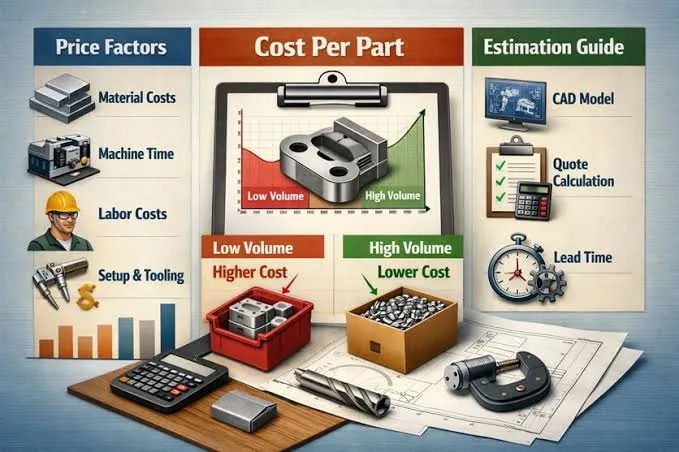
Setup and changeover cost is the other major factor. A simple turned part can often be set up in under 30 minutes with a collet or soft jaws. A multi-sided milled part may need several fixtures, multiple tool changes, and probing cycles. When volume is high, those differences compound quickly. For low-volume complex prismatic work the milling cost is accepted because there is no alternative; for medium-to-high volume rotational work, turning remains the lower-cost route.
Recommended Figure: Cost-breakdown bar chart comparing tooling, setup, cycle time, and material utilization for a typical shaft (turning) versus a typical housing (milling) at three volume levels.
What Happens During CAM Review and Production Planning
When a print arrives, the first question in CAM is not "which machine is free?" but "what is the dominant geometry?" If more than roughly 60–70 % of the features can be generated by rotation, the part is routed to turning or mill-turn. Fixturing is designed around the axis of rotation, soft jaws or collets are prepared, and the program is built around continuous OD/ID cuts with secondary live-tool operations only where necessary. If the part is largely prismatic, the CAM team designs fixtures that allow access to all required faces, often using multiple setups or a 4/5-axis strategy. Tool lists grow, cycle times lengthen, and the risk of collision or tool breakage increases.
Yield is usually higher on pure turning jobs because the process is more stable and fewer variables are in play. Milling yield drops when deep pockets, thin walls, or long tool overhangs appear. Process risk also differs: a broken insert on a lathe is usually a quick change; a broken end mill deep in a pocket can scrap the part and damage the fixture. Most shops therefore protect capacity on the mills for the work that truly requires them and push every suitable rotational part onto the lathes.
Practical Guidance on Which Process to Specify
Choose CNC turning when the part is predominantly rotational, when concentricity and roundness are critical, when volume is medium to high, and when you want the lowest cost and shortest cycle time. Even if a few milled features exist, a mill-turn center or a secondary milling operation after turning is still usually cheaper than milling the entire part.
Choose CNC milling when the geometry contains pockets, slots, 3D contours, or non-cylindrical surfaces that cannot be generated by rotation, when the part starts as plate or block stock, or when the features must be machined from multiple directions in a single setup. In those cases the extra cost and complexity of milling are simply the price of producing the required shape.
When both processes are feasible, the shop will almost always recommend turning first for the rotational features and milling only for the remaining non-rotational features. That sequence keeps the majority of the material removal in the more efficient process and reduces overall risk.
FAQs
Q1: Can a CNC mill completely replace a CNC lathe for round parts?
A1: Technically yes, but it is almost never economical. Generating true cylinders and concentric diameters with an end mill is slower, requires more complex tool paths, and usually produces inferior roundness and surface finish compared with a proper turning operation.
Q2: When does live tooling on a lathe become more expensive than a separate milling operation?
A2: When the milled features are deep, require many tool changes, or demand long cycle times. In those cases the mill-turn machine is occupied longer than necessary and a secondary op on a dedicated mill is often cheaper overall.
Q3: Which process gives better material utilization for high-volume production?
A3: CNC turning with bar feeders. Continuous bar feeding minimizes leftover stock and allows near-net material sizes. Milling from plate or block stock almost always leaves more scrap.
Q4: How do setup times typically compare?
A4: Pure turning setups are usually faster—collets or soft jaws and a short tool list. Multi-sided milling setups require more fixturing design, multiple zero points, and longer verification, so changeover time is higher.
Q5: Is there a volume threshold where milling becomes competitive for rotational parts?
A5: Rarely. Even at high volumes the continuous cutting and simpler tooling of turning keep it ahead on pure rotational geometry. Milling only becomes competitive when the part geometry itself forces prismatic features that turning cannot produce efficiently.
Q6: What should a designer do to make a part easier to manufacture on either process?
A6: Keep critical diameters and faces on a common axis of rotation whenever possible, minimize deep internal prismatic features, and call out reasonable surface finishes. Those choices let the shop route the part to the more efficient process and keep both cost and lead time down.