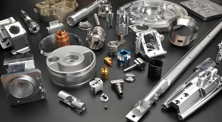
In production we load the CAD data straight into CAM software and generate toolpaths that match our machine capabilities and material behavior. CAM engineers check tool diameters against feature sizes, set stepover percentages based on material type, and apply compensation for tool deflection right from the start of the CNC machining process.

How CAM data translates into actual machine instructions on the shop floor
We see the CNC machining process start with verification of the imported geometry against our standard panel sizes. Most factories run multi-spindle drilling and routing machines where programs must account for stack height and backup material. Tool selection happens immediately after path generation — we match carbide bits to copper thickness and laminate type to avoid excessive heat buildup during drilling.
Rough machining removes the bulk of material at higher feeds while leaving stock for finishing passes. In our lines this stage uses larger diameter tools with aggressive stepovers, but we always monitor spindle load to prevent delamination on multilayer boards.
Material behavior that forces adjustments during the CNC machining process
FR-4 and other laminates expand and contract with temperature changes in the production environment. This shows up clearly when panels sit between processes — even a few degrees can shift hole positions enough to cause registration problems later. Tool wear also accelerates with glass fiber content, changing effective diameter mid-run if not monitored.
Panelization constraints add another layer. When we nest multiple boards on one panel, the CNC machining process must maintain consistent vacuum hold-down and avoid vibration that travels across the panel during high-speed routing.

What actually happens when tolerances drift during production runs
Uncontrolled tool deflection during finishing passes leads to out-of-tolerance hole diameters and slot widths. We have seen boards where the final routing left tabs that were too thin, causing panels to shift in subsequent plating or press cycles. In drilling, this appears as misregistration between layers that only becomes obvious after solder mask application.
Surface finish suffers when feed rates stay too high for the tool condition. This creates burrs that interfere with component placement or require extra deburring time. If ignored through the full CNC machining process, the batch can end up with yield drops of 15-25% once assembly partners start rejecting boards for dimensional issues.
Registration errors that compound across multiple CNC operations
Drilling first then routing without proper fiducial alignment causes cumulative offset. What we typically see is holes that no longer line up perfectly with the copper features after the panel has gone through etching and plating steps.
Factory-side adjustments that keep the CNC machining process under control
CAM engineers apply dynamic tool radius compensation based on measured tool wear from the previous job. We run test coupons on every new program to verify actual hole sizes before committing the full panel. Spindle speeds and feeds get adjusted according to material datasheets — typically 150,000-200,000 RPM for small diameter drills on FR-4 with peck cycles to clear chips.
During finishing we reduce stepover to 10-20% of tool diameter and add multiple light passes to control dimensional accuracy within ±0.05mm. Vacuum tables get calibrated daily and we use backup material like phenolic or aluminum entry sheets to prevent drill wander at entry and exit points.
For complex contours we break the CNC machining process into separate roughing and finishing programs. This lets us optimize each phase independently. Post-machining we run automated optical inspection that checks critical dimensions against the original CAD data and flags any deviation before the panel moves to plating.
Tool selection and parameter control that prevents common failures
We maintain a strict tool life database. A 0.3mm drill might only run 800-1200 holes before replacement depending on stack height. This data drives automatic tool change commands in the program so operators don’t rely on visual checks alone.
Surface treatment steps that follow directly after CNC operations
Once machining completes we move panels to deburring and then surface preparation for plating or coating. Any remaining burrs from the CNC machining process get removed mechanically or chemically before electroless copper to ensure good adhesion. This sequence matters because heat from plating can exaggerate any residual stress left from aggressive machining.
Quality checks built into every stage of the CNC machining process
First article inspection includes coordinate measuring machine verification of hole positions using fiducials. We compare results against the design intent and adjust offsets for the production run. In-line sensors on the machines monitor vibration and tool condition in real time, stopping the job if parameters drift outside preset limits.
Final electrical test and visual inspection confirm that the machined features support the intended functionality. Any boards showing routing inaccuracies get segregated before they reach packaging.
When we can relax some of the tighter controls
For simple single-layer prototypes or non-critical mechanical parts we sometimes allow wider tolerances on non-functional features. Quick-turn jobs with relaxed dimensional requirements can skip some of the intermediate verification steps, but we still maintain basic tool monitoring to protect the machines. The trade-off appears as slightly higher variation that assembly houses must accommodate.
High-volume standard boards benefit most from the full set of controls in the CNC machining process. Custom thick copper or exotic material panels almost always require the complete sequence because the material behavior becomes even less predictable.
From the production side, understanding these realities helps designers provide data that matches what our equipment can actually deliver consistently. The CNC machining process runs smoother when features respect the practical limits of tool size, material stability, and machine repeatability we work with every shift.