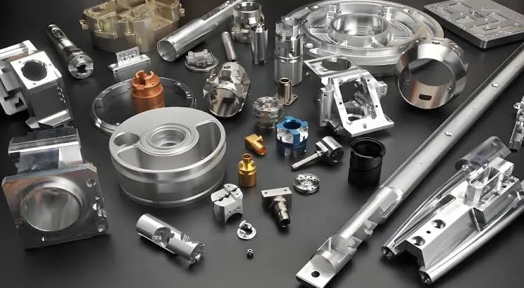
In production we treat CNC machining quality control as a locked sequence that starts the moment the first panel leaves the machine. CAM engineers load the verified program, set tool offsets from the previous run data, and the operator runs one first-article panel that goes straight to the inspection bench. Only after hole position, diameter, and routed outline clear the checks does the rest of the lot get released. That is the only way we keep multi-spindle drills and routers inside the registration window required for multilayer boards.
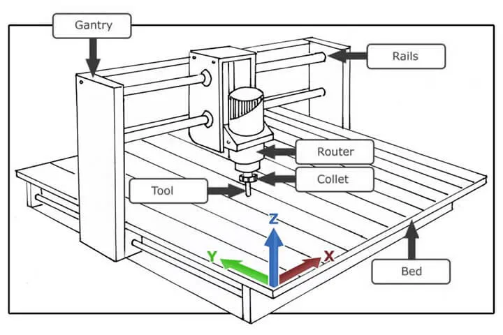
Why tool wear and thermal growth force the first-article lock
Every spindle on a production CNC router or drill grows 5–8 °C within the first hour of continuous running. Tool diameter drops by 0.015–0.025 mm after a few hundred holes once the coating starts to wear. Fixture clamping force varies panel-to-panel depending on copper thickness and stack-up. Those three factors alone push hole true-position and routed edge location outside the 0.05–0.075 mm window we hold for most multilayer jobs. The first-article measurement is the only practical way to catch the combined shift before the rest of the lot is committed.
Material behavior adds another layer. Different laminate suppliers bring different glass-transition temperatures and residual stress after lamination. When the CNC heat builds, the panel expands differently from the last lot, so the same program and the same tool offsets no longer land on the same coordinates. That is why we never rely on the previous job's offsets without a fresh first-article check.
What the scrap pile looks like when the sequence is skipped
Skip the first-article or let the dimensional checks slide and the next 50–100 panels come out with holes that break the annular ring or routed edges that undercut copper. Those boards either go to rework (if the customer still accepts the lead-time hit) or become scrap. Burrs left by a worn tool later cause plating voids or solder-mask adhesion failures downstream. The lot ships late while the machine is reset, the tool magazine is changed, and every panel already cut is re-inspected or written off. On high-layer-count boards the cost of that single missed check is measured in both money and customer schedule.
The inspection steps that actually run on every production lot
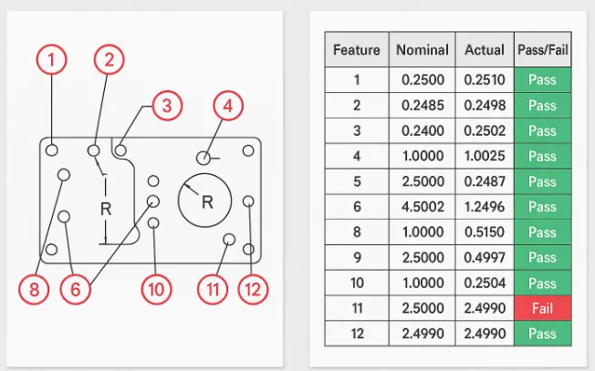
First-article inspection is done on a vision system or CMM within fifteen minutes of the panel leaving the machine. Hole diameter is checked with pin gauges or air gauges; X-Y true position and profile of routed outlines are measured on the CMM with a programmed probe path. Critical mechanical features (connector cut-outs, press-fit hole patterns, gold-finger edges) always go to CMM; non-critical outlines stay on the vision system for speed.
Surface roughness is sampled on every routed edge that will later see plating or solder mask. We use a portable profilometer and hold Ra 1.6 µm or better unless the drawing calls for tighter. Material verification is the simple but mandatory step of matching the laminate lot number and copper foil certificate against the traveler before the job starts. Any mismatch stops the run.
Every lot closes with a quality report that contains the first-article data sheet, the CMM printouts for critical features, SPC charts for the key dimensions, and the roughness readings. That package travels with the panels to the next process and is archived for customer audit. For new tool or laminate suppliers we run a short capability study (minimum 30 panels) and require Cpk ≥ 1.33 on the critical dimensions before the supplier is released for production use.
Where limited relaxation is allowed and where it is not
On low-volume prototype runs with open mechanical tolerances (±0.15 mm) and non-critical outlines we sometimes release after a reduced first-article check if the customer signs a formal deviation. High-reliability, impedance-controlled, or high-layer-count boards never receive that relaxation; the full sequence stays locked. Tool-life limits are also never relaxed—once the tool reaches the wear limit recorded in the machine's tool-management system it is changed regardless of remaining panel count. That rule alone prevents most of the dimensional drift we used to see before tool-life tracking was enforced.