Every so often a maker project walks in that still makes the factory floor pause for a second. TechTalkies' ESP32-S3 USB Host build is exactly that kind of project.
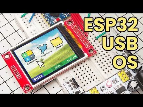
The question that started it all was almost playful: what if an ESP32-S3 could act like a real computer? In the video a live mouse cursor glides across a 160×128 ST7735 screen, real keyboard presses appear the instant they are typed, a USB flash drive mounts and lets the user browse folders and open text files, and finally a complete mini OS appears—complete with file explorer, calculator and a tiny bird game—all running on a board that most people only ever use for Wi-Fi projects.
TechTalkies wasn't chasing another quick demo. The goal was to prove that a microcontroller could host genuine USB peripherals, present a familiar desktop interface, and still feel approachable. The hardware stayed deliberately simple: an ESP32-S3 Super Mini, an ST7735 TFT, an OTG adapter, a USB hub, a mouse, a keyboard and a flash drive. The software (EspUsbHost plus Adafruit ST7735 and GFX libraries) did the clever work. But anyone who has lived through the gap between a working breadboard and a product that feels finished knows the next step is non-negotiable: a clean, manufacturable PCB that can actually deliver the performance the firmware promises.
Figure: Mini computer hardware
When a Tiny Screen Starts Feeling Like a Real Desktop
The mouse test is pure joy. Plug in an ordinary USB mouse and a crisp cursor appears, clamped at the edges so it never vanishes. Move the mouse and the pointer tracks instantly—no lag, no jitter. For a chip most makers treat as a Wi-Fi gadget, watching it host a real HID mouse already feels like a small miracle.Figure: Mini computer hardware
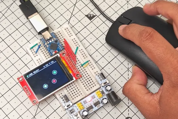
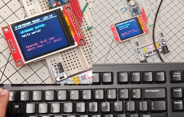
Keyboard input follows just as cleanly. Key-presses show up live, complete with the hexadecimal codes underneath. Suddenly the little board stops being a microcontroller and starts feeling like an input device.
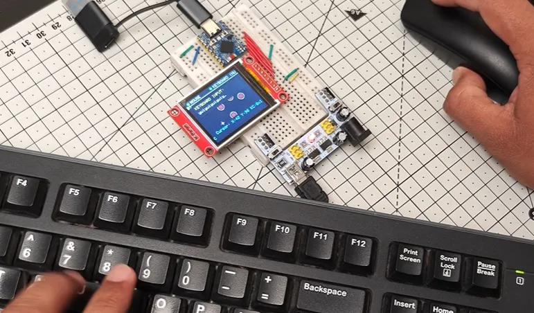
The dual-mode demo pushes things further: a USB hub lets mouse and keyboard run together. Two HID devices enumerate, both live, both responsive. That single moment quietly proves the ESP32-S3's native USB Host capability can handle concurrent devices without drama.
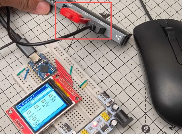
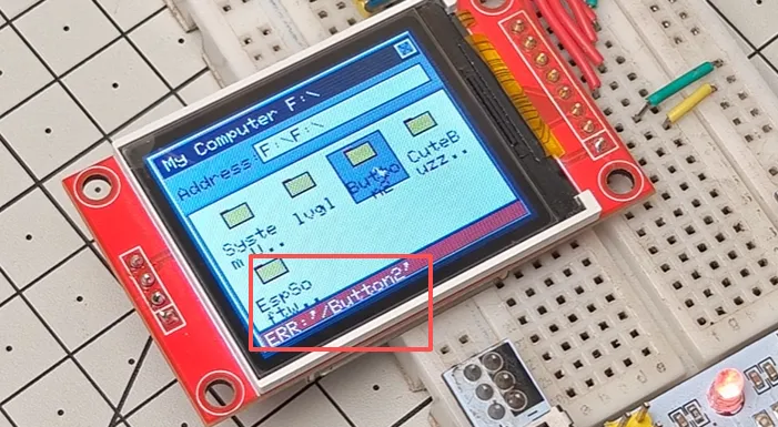
Then the mass-storage test lands. A USB flash drive mounts, the root directory appears in a Windows 95-style file explorer, and a mouse click opens a text file for preview. The firmware later expands into a proper mini-OS with file explorer, calculator and a playable bird game. Everything is driven from the same small board that already sits in most makers' drawers.
What makes these demos stick is not just that they work—it is that they feel intentional. The UI is retro and charming rather than clinical. Feedback is immediate. You can almost hear the creator thinking, "If this tiny thing can do this, what else is possible?"
Behind the fun sit some very real hardware decisions. USB Host only works through the native pins (GPIO 19 and 20).
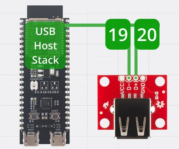
The UART bridge port will not help. Power for the peripherals has to be supplied correctly. The SPI lines to the ST7735 need to stay clean. And once a hub, mouse, keyboard and storage are stacked together, the system has to remain stable under real current draw and real signal conditions.
The Quiet Engineering That Keeps USB Host Reliable
Moving from a temporary Super Mini plus flying wires to a board people can actually use requires deliberate layout choices. Here are the parameters that turn a clever demo into something manufacturable:
|
Parameter |
Target Value |
Reason |
|---|---|---|
|
Layers |
4-layer |
Continuous ground plane under USB and SPI |
|
Board thickness |
1.6 mm |
Mechanical rigidity for connectors |
|
Material |
FR-4, Tg 150 °C |
Cost-effective yet stable for makers |
|
Copper weight |
1 oz outer / 0.5 oz inner |
Solid current handling for USB 5 V |
|
Surface finish |
ENIG |
Reliable for USB and display connectors |
|
USB differential pair |
90 Ω ±10 % |
Full-speed USB Host integrity |
|
Via type |
Through-hole + microvias where needed |
Clean transitions on USB traces |
|
Min trace/space |
5 / 5 mil |
Controlled impedance achievable |
The D+/D– pair must be routed tightly coupled, length-matched, with a continuous ground reference and as few vias as possible. Series resistors and the required capacitors sit close to the ESP32-S3. SPI lines to the ST7735 stay short and well clear of the USB pair. A dedicated 5 V rail with proper decoupling ensures the board can actually power a mouse, keyboard or flash drive when acting as Host.
The Friction That Shows Up Between Demo and Product
A subtle software-side friction appeared during the mass-storage tests. When a USB flash drive was inserted, the mini computer correctly detected the drive and displayed the root directory folders. The root contents were readable. Yet opening any of those folders revealed nothing—the subfolder contents simply refused to appear. This partial success is classic in early USB Host + MSC development: basic enumeration and FAT root reading work, but deeper directory traversal still needs refinement. On a noisy or power-unstable breadboard setup, these kinds of intermittent software gaps become much harder to isolate and fix.
Where Professional Manufacturing Quietly Raised the Bar
This is where the partnership quietly changes the outcome. TechTalkies already had the firmware vision and the working demos. What was still needed was a board that could host multiple USB devices reliably, drive the display cleanly, supply clean power, and still look and feel like a finished little computer rather than a tangle of modules.
AIVON's role was to turn that vision into a manufacturable reality. The design started with a four-layer stack-up that provided a solid, continuous ground plane under the critical USB differential pair. Controlled-impedance routing for the 90 Ω D+/D– lines was verified against the actual stack-up, not just a calculator estimate. The pair was kept short, matched, and free of unnecessary vias; where a layer change was unavoidable, ground return vias were placed immediately beside the signal vias.
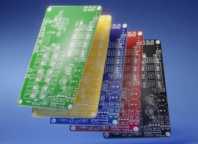
Power distribution received equal attention. A dedicated 5 V rail with generous copper and multiple decoupling capacitors near the host connector ensured that a mouse, keyboard and flash drive could all draw current without collapsing the supply. The SPI bus to the ST7735 was routed away from the USB pair and given its own clean return path so the Windows 95-style UI stayed sharp and lag-free.
DFM checks caught the small things that kill prototypes: silkscreen clearance around the USB connector, proper solder-mask expansion on the fine-pitch ESP32-S3 pads, and test points that let the creator verify USB enumeration without desoldering anything. The result was a board that not only worked on the first power-up but kept working when the hub, mouse, keyboard and storage were all active at once.
The custom PCB did more than fix problems—it elevated the project. The live cursor became smoother, device detection more consistent, and the whole system stable enough that the mini-OS demos could be shown with confidence. What started as a clever Super Mini experiment became something that felt product-ready. That is the quiet power of treating the PCB as an engineering partner rather than an afterthought.
DFM Checklist for ESP32-S3 USB Host + TFT Projects
|
Check Item |
Why It Matters |
Pass Criteria |
|---|---|---|
|
USB D+/D– length match |
Prevents enumeration failures |
< 5 mil difference |
|
90 Ω differential impedance |
Full-speed signal integrity |
±10 % verified |
|
Continuous ground under USB pair |
Return path integrity |
No splits under traces |
|
5 V rail copper width & decoupling |
Host must power peripherals |
≥ 1 A continuous capability |
|
SPI length and separation from USB |
Clean display updates |
< 50 mm, > 3× spacing |
|
Connector mechanical support |
Survives repeated plug/unplug |
Mounting holes or stiffener |
|
Test points on USB D+/D– and 5 V |
Fast bring-up and debug |
Accessible without tools |
A Finished Board That Still Feels Like Play
Watching TechTalkies turn a humble ESP32-S3 into a recognisable little computer is pure maker joy. The mouse cursor, the live keyboard, the flash-drive file browser and the cheeky mini-OS all prove that ambitious ideas can live on surprisingly small hardware—provided the PCB underneath is solid.
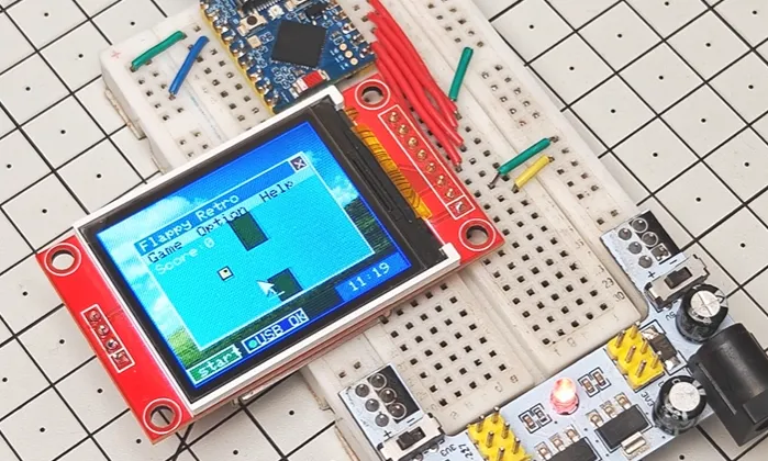
The journey from Super Mini plus OTG adapter to a clean, reliable custom board is the part that often decides whether a cool demo stays a one-off or becomes something others can build and enjoy. Helping a creator's vision survive contact with real manufacturing reality and come out stronger is what makes projects like this memorable.
If an ESP32 idea needs to host real peripherals, drive a sharp display, or simply stop living on a breadboard, the same path is open. Design carefully, respect the differential pairs and the power rails, and partner with a manufacturer that treats the prototype as seriously as the creator does. The little mini computer on the bench is only the beginning.
FAQ
Q1: Does the ESP32-S3 really support full USB Host without external PHY chips?
A1: Yes. The ESP32-S3 has a native USB OTG peripheral. The dedicated D+/D– pins (usually GPIO 19/20) must be used and proper 5 V power provided to the devices. No external PHY is required for full-speed Host operation.
Q2: Why is controlled 90 Ω impedance so important on a USB Host board?
A2: Even full-speed USB can fail to enumerate or drop packets if the differential pair is poorly matched or poorly referenced. On a custom PCB the cost of getting the impedance right is almost zero; the cost of debugging intermittent detection is high.
Q3: Can a USB mouse, keyboard and flash drive be powered directly from the ESP32-S3 board?
A3: Yes, provided the 5 V rail and its regulator (or input) can supply the combined current. The power path should always be designed with adequate copper and local decoupling near the host connector.
Q4: What is the biggest DFM mistake people make with ESP32-S3 USB Host designs?
A4: Bringing the native USB pins out through long, unmatched, or unshielded traces, or relying on the UART USB port. The second most common error is forgetting that the Host must supply 5 V to the peripherals.
Q5: Is a 2-layer board good enough for this kind of project?
A5: Possible for very short runs and light loads, but a 4-layer board with a continuous ground plane makes the USB pair and SPI bus dramatically more reliable and is still inexpensive at prototype quantities.
Q6: How does one move from the Super Mini + OTG setup to a real product?
A6: Capture the working pinout and power requirements, design a board with proper USB differential routing, a solid 5 V host supply, and a clean display interface, then run a full DFM check before ordering. That single step turns a clever demo into something that can be shared with confidence.