The glass transition temperature (Tg) of a printed circuit board (PCB) is the temperature at which the laminate's polymer matrix transitions from a glassy, rigid state to a rubbery, viscoelastic state. This transition marks a distinct change in the material's physical and mechanical properties. Because modern surface-mount technology (SMT) reflow profiles expose assemblies to high temperatures, Tg is a critical parameter that directly influences assembly yield, dimensional stability, and long-term reliability.
Below the Tg, the laminate exhibits high stiffness and dimensional stability. As temperature approaches and exceeds Tg, the modulus drops sharply, the material softens, and the coefficient of thermal expansion (CTE) generally increases, especially in the out-of-plane (z-axis) direction. These changes can affect both mechanical integrity and electrical performance during manufacturing and operation.
What Tg Represents in PCB Laminates
Tg reflects the thermal stability and mechanical strength of the PCB laminate under elevated temperatures. If the in-process or operating temperature reaches or exceeds Tg, the material begins to lose rigidity and may deform. This can reduce the mechanical strength of the board and, under some conditions, impact electrical performance through dimensional changes that affect trace geometry, layer registration, and component coplanarity.
A higher Tg laminate maintains better performance when exposed to high temperatures. Such materials are well suited to products that run hot in service or must endure aggressive assembly profiles and multiple thermal excursions. It is important to understand that Tg is not a single, infinitely precise temperature; it is a transition region whose reported value depends on the measurement method and the chosen definition of the transition point.
Classification of PCBs by Tg
-
Low-Tg PCBs: Laminates with lower Tg values, typically below 100 °C, suited to low-temperature applications where thermal stability demands are modest.
-
Medium-Tg PCBs: Laminates with Tg generally in the 150–180 °C range. These materials provide good performance and reliability across a moderate thermal envelope and are widely used in general-purpose electronics.
-
High-Tg PCBs: Laminates with Tg values exceeding 180 °C. These materials are appropriate for applications that require extended operation at elevated temperature, high power density, or that must withstand demanding assembly profiles with improved thermal stability and mechanical strength.
Measuring Tg and Material Factors That Influence It
Tg can be characterized by several analytical methods. Common approaches include differential scanning calorimetry (DSC) and dynamic mechanical analysis (DMA). DSC observes changes in heat flow associated with the glass transition, while DMA measures changes in viscoelastic properties (such as storage modulus and tan delta) as temperature increases. Because each method defines the transition differently, the measured Tg can vary between methods and even between different analysis criteria within the same method.
The Tg of a PCB laminate is primarily governed by the resin chemistry and its crosslink density. Common resin systems include epoxy, polyimide, and polyamide, each with distinct thermal stability. In addition to base chemistry, formulation and processing details also matter, such as curing conditions, resin content, filler concentration, and glass reinforcement. These factors collectively determine the onset of the glass transition and how sharply properties change across it.
Implications for SMT Reflow Soldering
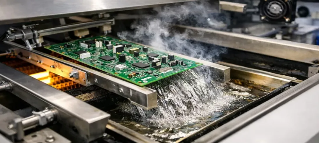
During SMT reflow, the assembly experiences a controlled thermal cycle with preheat, soak, peak, and cooling stages. Lead-free reflow profiles often push PCB laminates near or above the Tg of standard materials. When the laminate spends time above Tg, its reduced stiffness and increased CTE can influence several assembly outcomes:
-
Board and package warpage. Above Tg, the laminate softens and can warp due to copper asymmetry, uneven heat input, or package-induced stress. Warpage deteriorates coplanarity at the solder interface, which can cause opens and shorts under area-array devices, head-in-pillow defects on BGAs, and inconsistent solder joint formation on fine-pitch leads.
-
Dimensional stability and registration. The transition through Tg can alter board dimensions temporarily during the peak dwell. For dense designs, this affects solder paste alignment, stencil-to-pad registration, and placement accuracy, especially on thin panels or boards with significant copper imbalance.
-
Z-axis expansion and interconnect stress. The out-of-plane CTE increases above Tg, which adds stress to plated through-holes, microvias, and interfacial regions like pad-to-laminate. Repeated thermal excursions during double-sided reflow or rework can accumulate damage and reduce interconnect reliability.
-
Mechanical robustness under large packages. Large BGAs and LGA packages create localized stress during thermal cycling. When the laminate is above Tg, reduced modulus can contribute to pad cratering or interfacial cracking if the stackup and copper distribution are not well balanced.
Using a higher-Tg laminate can widen the process window by maintaining higher stiffness at peak temperatures, reducing warpage and improving coplanarity during solder reflow. However, Tg is only one aspect of assembly robustness. Stackup symmetry, copper balancing, panel design, and fixturing also play important roles, especially for large-format or thin boards.
Design and Process Considerations to Mitigate Tg-Related Risks
-
Select appropriate Tg with margin to the reflow profile. For assemblies with demanding thermal profiles, choose a laminate with a Tg that provides sufficient margin relative to the expected peak temperature and dwell time. This reduces time spent in the softened regime and improves dimensional stability at peak.
-
Use symmetric, copper-balanced stackups. Symmetry and copper balance across layers minimize differential expansion and warpage. Avoid large, unbalanced copper planes or heavy copper concentration on one side of the stack, particularly for thin cores and prepregs.
-
Control board thickness and panelization. Thicker boards are generally less prone to warpage, while very thin boards require additional support. Optimize panelization breakaway features and include tooling rails to improve handling and reduce deformation.
-
Provide adequate mechanical support during reflow. Use carriers, pallets, or center supports for thin boards or assemblies with heavy components to maintain planarity at elevated temperature and reduce coplanarity-induced defects.
-
Minimize thermal cycles. Limit the number of reflow passes and rework operations. For double-sided assemblies, consider placing large or warp-sensitive packages on the second side only when necessary and coordinate the profile to control time near or above Tg.
Selecting a Suitable Tg for Your Design
Choosing an appropriate Tg is essential to ensure the PCB maintains performance and reliability under expected assembly and operating conditions. Practical selection should consider:
-
Operating environment. Account for ambient temperature, internal heating from power dissipation, and any sustained exposure to elevated temperatures during product use.
-
SMT reflow profile. Align material selection with the assembly profile, including peak temperature, dwell duration, and the number of reflow cycles. A laminate with higher Tg provides additional stability during peak and may improve yield for thermally challenging assemblies.
-
Design geometry. Thin boards, high layer counts, large copper pours, and dense area-array packages increase sensitivity to dimensional changes around Tg. Higher Tg materials can mitigate these sensitivities.
-
Material system. Epoxy-based materials dominate mainstream applications and span a wide Tg range. Polyimide and other high-performance systems offer higher Tg and thermal stability for more demanding environments.
-
Manufacturing capability and cost. Higher Tg materials may require specific lamination cycles and can be more costly. Coordinate with your PCB fabricator and assembler to ensure the selected laminate is compatible with their processes and your cost targets.
During material comparison, be mindful of how Tg was measured. DSC- and DMA-derived Tg values may not be directly comparable. When possible, use data obtained by the same method and criteria to ensure consistent evaluation.
Conclusion
Tg is a fundamental laminate property that strongly influences PCB behavior during SMT reflow. As the board passes through the glass transition region, stiffness and expansion characteristics shift, affecting warpage, coplanarity, dimensional stability, and interconnect reliability. Selecting a laminate with an appropriate Tg and designing the stackup and panel to control warpage will improve assembly yield and product reliability. Integrating material choice with reflow profiling, copper balance, and mechanical support provides a robust path to high-quality solder joints and stable long-term performance.
Appendix: Summary Points
-
Tg indicates the glass-to-rubber transition of the PCB resin system and marks a change in mechanical behavior.
-
Low-, medium-, and high-Tg materials target different thermal and reliability requirements: below 100 °C, 150–180 °C, and above 180 °C, respectively.
-
Tg is commonly measured by DSC or DMA; values depend on method and criteria.
-
For SMT reflow, adequate Tg margin, stackup symmetry, copper balance, and mechanical support are key to minimizing warpage and defects.
-
Choose Tg based on operating temperature, assembly profile, design geometry, material system, and manufacturing capability.