Sn-Ag-Cu (SAC) lead-free solders are the primary interconnect materials in modern electronic packaging. Their long-term service reliability is governed by the interaction of multiple physicochemical processes. Based on experimental evidence and consolidated literature, four core factors drive the reliability of SAC joints end-to-end—from manufacture through field failure: alloy composition and microstructure evolution, interfacial intermetallic compound (IMC) behavior, fatigue under thermo-mechanical coupling, and the role of process parameters. Together, these dimensions form the main thread of performance evolution for solder joints.
First, alloy composition sets the intrinsic properties of the solder. Ag and Cu content directly affect the precipitation morphology and number density of Ag3Sn and Cu6Sn5 phases. Data show that 95.4Sn/3.1Ag/1.5Cu delivers an optimal balance of mechanical properties and fatigue life when Ag is at 3.0%–3.1% and Cu at about 1.5%. Excess Ag (>4.1%) coarsens Ag3Sn, reducing ductility and fatigue resistance1. Minor additions of Ni, Bi, In, or rare-earth elements (e.g., Ce) can significantly improve reliability via second-phase strengthening, IMC growth suppression, or improved strain accommodation.
Second, the formation and evolution of interfacial IMCs are pivotal to joint life. The scallop-like Cu6Sn5 layer formed during initial reflow offers good bonding, but it thickens and coarsens during thermal cycling or aging. When its thickness exceeds roughly 3–4 μm, brittle failure mechanisms dominate and cracks readily propagate along the IMC/Sn interface. Over long service, a Cu3Sn layer may form along with Kirkendall voids, further weakening interfacial strength. IMC growth is diffusion-controlled, follows a square-root-of-time relationship, and shows composition-dependent activation energy. Among typical SAC alloys, Sn-3.4Ag-0.7Cu exhibits the highest thermal stability (70.50 kJ/mol).
Third, fatigue behavior under thermo-mechanical coupling determines durability in real operating conditions. Due to the significant coefficient of thermal expansion (CTE) mismatch between chip (Si: ~2.6 ppm/°C) and substrate (FR-4: ~16–18 ppm/°C), joints experience alternating shear stresses during temperature cycling. Von Mises stress may reach ~200 MPa, far exceeding the yield strength of SAC305 (about 50 MPa). Cracks typically initiate at corner joints and grow along the IMC, ultimately causing opens. Fatigue life can be accurately predicted by a modified Coffin–Manson model, with errors within about 2% in validated cases.
Finally, process parameters strongly influence microstructure and residual stress. Reflow profile (peak 235 °C ± 5 °C, 40–60 s above liquidus, cooling ≤ 2 °C/s), limits on multiple reflows (≤ 2), underfill application (fill ratio ≥ 95%), and surface finish selection (ENIG over OSP) are all effective at retarding IMC growth, lowering stress concentrations, and improving overall reliability.
These four factors are interrelated and evolve dynamically, forming a complex multiscale reliability degradation network. The following sections develop these core viewpoints with data and mechanism-based analysis to provide a technical basis and optimization path for high-reliability electronics.
2. Alloy Design and Microstructure Evolution
Alloy composition is the foundation of the intrinsic performance and long-term reliability of Sn-Ag-Cu solders. The Ag/Cu ratio governs the precipitation morphology and distribution of IMCs and the overall microstructure of the solder, directly affecting strength, ductility, fatigue resistance, and degradation under thermo-mechanical loading. This section explains the optimization mechanisms of Ag/Cu ratios, microalloying strategies, the synergistic strengthening of multiphase structures, and development trends in composite solder systems.
2.1. Effects of Ag/Cu Ratio on Mechanical Properties
In the ternary Sn-Ag-Cu system, Ag and Cu contents jointly and nonlinearly affect yield strength, tensile strength, ductility, and fatigue life. When silver is around 3.0%–3.1%, yield and tensile strength increase nearly linearly with copper up to ~1.5% Cu; beyond that, yield starts to decline while tensile strength tends to plateau. Ductility remains relatively high for 0.5%–1.5% Cu, then decreases as Cu rises further.
Fatigue life is particularly sensitive to the Ag/Cu balance. With 3.0%–3.1% Ag, the maximum fatigue life occurs near 1.5% Cu. The 95.4Sn/3.1Ag/1.5Cu composition is often optimal, producing fine microstructure and an efficient dispersion of Cu6Sn5 particles that synergize with Ag3Sn to deliver a strong strength–ductility–fatigue balance.
Raising Ag above this range does not necessarily improve properties. For example, increasing Ag up to 4.7% does not yield further mechanical gains; instead, Ag3Sn coarsens into large plates or particles that negate the benefit of increased phase fraction, reducing fatigue life. With simultaneously high Ag and Cu (e.g., 96.3Sn/4.7Ag/1.7Cu), ductility degrades. In short, chasing short-term strength by elevating Ag and Cu can sacrifice long-term fatigue and ductility, posing reliability risks.
| Alloy (Sn-Ag-Cu) | Key Mechanical Performance | Primary Reliability Impact |
|---|---|---|
| 95.4Sn/3.1Ag/1.5Cu | High yield and tensile strength; good ductility; maximum fatigue life. | Best overall balance; high reliability. Fine Ag3Sn and Cu6Sn5 provide optimal dispersion strengthening. |
| 93.6Sn/4.7Ag/1.7Cu | Highest tensile strength, but ductility far below 63Sn/37Pb; fatigue life inferior to 95.4Sn/3.1Ag/1.5Cu. | High strength but low ductility; increased brittleness; weaker fatigue resistance. |
| 95.4Sn/4.1Ag/0.5Cu | Lower yield strength than 95.4Sn/3.1Ag/1.5Cu. | Not optimal strength; insufficient Cu may reduce Cu6Sn5 strengthening. |
| High-Ag variants (>4.1%) | Ag3Sn coarsening; ductility reduction. | Coarse Ag3Sn acts as crack initiators, accelerating fatigue failure and lowering reliability. |
2.2. Microalloying Strategies
To push beyond baseline SAC performance—especially fatigue resistance under severe thermal cycling—microalloying is effective. Trace additions of Ni, Bi, In, or rare-earth elements (e.g., Ce) can tune interfacial reaction kinetics, microstructure, and mechanical response.
Ni + Bi co-doping shows strong synergy. Adding 0.1 wt% Ni and 0.05 wt% Bi to Sn-Ag-Cu reduces interfacial IMC growth rate by 47%. Under -40 °C to 125 °C thermal cycling, the modified joints reach 2850 cycles to failure versus 1620 cycles for standard SAC305, a 75.3% increase. Mechanistically, Ni suppresses Cu diffusion into the solder and slows IMC thickening, while Bi's crystal structure enhances strain accommodation and mitigates stress concentration.
Indium can improve thermal stability. In Sn-3Ag-3Sb-xIn (x = 1–5 wt.%), IMC growth is significantly suppressed when In ≥ 3 wt.%. InSb particles enrich at the IMC surface, forming an InSb "barrier layer" that impedes atomic diffusion and pins IMC grain boundaries, curbing coarsening. Over 1080 h of high-temperature aging, the shear strength decay rate can be as low as ~0.0039 N/h, comparable to some commercial high-reliability solders (SnAgCuBiSbNi), with more ductile or quasi-ductile fracture modes. In -55 °C to 150 °C thermal shock, Sn-3Ag-3Sb-5In achieves a characteristic life of 1858 cycles, 50% higher than Sn-3Ag-0.5Cu (1237 cycles).
Rare-earth additions (e.g., Ce) enhance fatigue life through microstructural strengthening. Adding ~0.03% Ce to Sn-3.8Ag-0.7Cu (SnAgCuCe) reduces stress–strain response in thermal cycling versus undoped SnAgCu in finite element analyses. Ce introduces second-phase particles that pin dislocations and lower plastic strain amplitude. Predicted fatigue life for CSP36 joints improves significantly with Ce, confirming its positive reliability impact.
2.3. Synergistic Strengthening of Multiphase Microstructures
Reliability depends not only on alloy composition but also on the evolving multiphase microstructure during manufacturing and service. After reflow, Ag3Sn often appears as fine particles or a network encasing Sn grains, producing strong dispersion strengthening and high initial strength.
However, during reliability testing—especially thermal shock—this Ag3Sn network can degrade. The network fractures and transforms into discrete particles, more readily under thermal shock than steady high temperature. The transition from a continuous network to discrete particles weakens constraint on the Sn matrix and shifts stresses to interfaces between coarse Ag3Sn and Sn, promoting microcrack initiation and lowering joint strength. This microstructural degradation is a key intrinsic mechanism of performance decay under thermo-mechanical coupling.
2.4. Emerging Composite Solder Systems
New applications such as flexible electronics and high-density packaging (e.g., 3D stacking, chiplets) demand both low-temperature assembly and high reliability, driving innovation in composite solder systems.
Sn-Bi low-temperature eutectic (~139 °C) reduces thermal input, mitigating CTE-mismatch stress and protecting temperature-sensitive components and substrates. Studies indicate crack growth in the IMC can be reduced by ~70% during thermal cycling. However, Bi additions require caution. For example, in Sn-2Ag-0.75Cu-3Bi joints to Sn-Pb plated leads, high-temperature exposure can accelerate interfacial alloy growth and form Pb-rich layers, suspected to contain low-melting Sn-Pb-Bi eutectic, lowering joint strength. Proper pairing with surface finish is therefore critical.
A "dual-layer ball" concept represents structural innovation. In FCLGA, a bottom high-melting SnAg3.5 layer (221 °C) and a top low-melting SnBi58 layer (139 °C) can be used. The bottom layer remains solid after reflow, providing a robust mechanical/electrical anchor, while the top layer absorbs mismatch strain energy during subsequent assembly or service, shielding brittle IMCs from stress. This melting-point gradient addresses both connection strength and environmental compliance.
Nanodoping—such as adding Mo nanoparticles or Ag3Sn nanoparticles—introduces second-phase strengthening, impedes dislocation motion, and suppresses IMC growth. These composites have been shown to improve hardness, tensile strength, and fracture toughness, pushing solder technology toward composition–structure–process co-design.
3. Interfacial Reactions and IMC Growth Kinetics
The formation and evolution of IMCs at the joint interface largely determine SAC solder reliability. As the metallurgical bridge between solder and substrate, IMC type, thickness, morphology, and growth kinetics govern mechanical strength and failure modes. This section covers IMC formation, diffusion-controlled growth, thermal stability, and size effects in miniaturized joints.
3.1. IMC Types and Formation Mechanisms
During SMT soldering, elevated temperature drives interdiffusion of Sn and substrate metals (primarily Cu), forming interfacial IMCs via specific reaction paths.
With a pure Cu substrate, two IMCs are typically observed. Within 3–5 s of contact with molten solder, a thin Cu6Sn5 (η) layer forms, enabling good metallurgical bonding. With continued thermal exposure or isothermal aging, Cu diffuses through Cu6Sn5 and forms a Cu3Sn (ε) layer between Cu6Sn5 and the Cu substrate. During long-term aging, Cu3Sn thickens and may be accompanied by Kirkendall voids concentrated near Cu3Sn/Cu, degrading both mechanical and electrical properties. Plated or sputtered Cu with columnar grains/impurities is more prone to voiding than high-purity Cu.
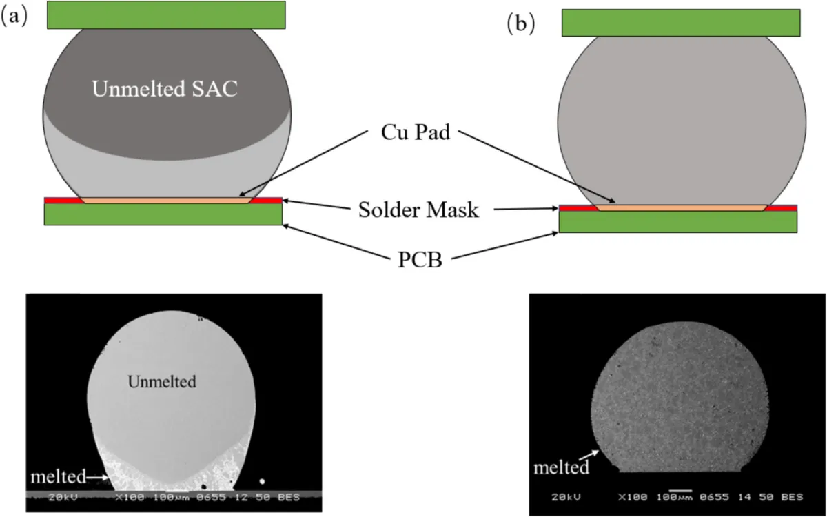
On ENIG/ENEPIG finishes, the Ni barrier participates in reactions and forms Ni-containing IMCs. Ball size strongly influences resultant IMCs. For 200 μm Sn-3.0Ag-0.5Cu balls on ENEPIG, (Ni,Cu)3Sn4 forms (Ni3Sn4 with some Cu in solution). For 400 μm balls, (Cu,Ni)6Sn5 forms (Cu6Sn5 with some Ni). At 300 μm, both phases may appear, with (Cu,Ni)6Sn5 near the substrate and (Ni,Cu)3Sn4 near the solder. This size effect arises because small joints contain less total Cu, favoring Cu-lean (Ni,Cu)3Sn4.
3.2. IMC Growth Laws and Control Targets
IMC growth is diffusion-controlled; thickness δ typically follows a parabolic law with time t, δ = k√t. During cooling, growth can become interface-reaction-controlled, following h = ktn with n ≈ 1, described by the precipitation flux controlled (PFC) model. Temperature is critical: a 10 °C increase can accelerate growth by a factor of 2–3. For example, at 150 °C, Cu6Sn5 formation rates can reach ~3.8 nm/√s. Multiple reflows drive secondary growth: after four reflows, interfacial IMC can increase from ~1.2 μm to ~4.5 μm, crossing a brittle threshold and raising field failure from ~0.3% to ~12%.
Industry acceptance ranges are well established. Per IPC-J-STD-001, 0.5–3 μm IMC thickness is acceptable for SAC joints. Layers thinner than 0.5 μm risk poor bonding and opens; layers thicker than 3 μm are brittle crack paths under cycling. For high-reliability applications (e.g., medical, automotive), tighter limits are used: after 1000 thermal cycles, growth should be ≤ 1 μm and total thickness ≤ 4 μm.
3.3. Diffusion Control and Activation Energy
Arrhenius behavior quantifies IMC growth: k = k0 exp(-Q/RT), where Q is apparent activation energy. Higher Q indicates lower temperature sensitivity and better thermal stability.
For different Ag levels on Cu at 150 °C, measured activation energies (Cu6Sn5 + Cu3Sn growth) are:
- Sn-3.0Ag-0.7Cu/Cu: 67.13 kJ/mol
- Sn-3.4Ag-0.7Cu/Cu: 70.50 kJ/mol
- Sn-3.8Ag-0.7Cu/Cu: 69.54 kJ/mol
Sn-3.4Ag-0.7Cu shows the highest Q, i.e., the slowest IMC growth at elevated temperatures and superior thermal stability. Morphology evolves from initial scallops toward more planar, interface-normal growth in late aging. Finite element analyses indicate thermal stress localizes at the Cu3Sn/Cu boundary; equivalent creep strain increases with aging time, steadily reducing reliability.
3.4. Size Effects and Microbump Challenges
With ongoing miniaturization, solder joint dimensions shrink into the micrometer regime, amplifying size effects in IMCs and complicating reliability control. In 30 μm microbumps, IMCs can occupy up to ~60% of the joint volume, which shifts mechanical response toward brittle behavior. Low Cu content in small joints also biases IMC selection toward (Ni,Cu)3Sn4 on ENIG/ENEPIG.
Size effects couple IMC growth with mechanics. In Sn-3.0Ag-0.5Cu/ENEPIG joints, both IMC thickness and shear strength decrease with increasing ball diameter at the same reflow count. After one reflow, 200 μm balls shear at ~87 MPa, 300 μm at ~68 MPa (-21.5%), and 400 μm at ~60 MPa (-5.5%). Fractography is consistent: larger joints show more cleavage-like regions (better global plasticity), whereas smaller joints show larger tearing areas.
Microbumps also challenge metrology. Conventional SEM struggles to resolve nonuniform IMC thickness in micrometer-scale joints. Meanwhile, flexible electronics push low-temperature assembly (T < 150 °C), motivating low-activation-energy IMC systems or low-temp solders (e.g., Sn-Bi) to reduce thermal stress while controlling interfacial reactions. Real-time monitoring is being explored, such as embedded sensors tracking resistance changes as an early indicator of IMC growth.
4. Fatigue Failure in Thermo-Mechanical Environments
In service, solder joints are exposed to coupled temperature changes and mechanical loads. This coupling drives fatigue and dictates long-term reliability. This section analyzes CTE-mismatch-driven stress concentration, crack initiation and growth, life prediction models, and thermally driven atomic migration.
4.1. Stress Concentration from CTE Mismatch
In flip-chip structures, large CTE differences among silicon, organic substrates, and PCB produce substantial thermo-mechanical loads: silicon ~2.6 ppm/°C, organic substrates ~12–17 ppm/°C, FR-4 ~15–18 ppm/°C. During thermal or power cycling, the solder joints—being the only mechanical interconnect—see alternating shear and bending stresses.
Finite element analyses show that under -40 °C thermal shock, Von Mises stress at joint edges can reach ~200 MPa, far above the ~50 MPa yield of SAC305. Stress concentrations are strongest at geometric discontinuities, especially corner/edge joints. For large packages (> 35 mm) with I/O density > 100 I/O/cm2, corner-to-center joint stress can differ by up to ~2.7×2. The absence of leadframes in flip-chip further increases joint loading; bending can contribute ~35%–42% of total stress. This highly localized, CTE-mismatch-dominated stress field provides the mechanical conditions for microcrack nucleation.
4.2. Crack Initiation and Growth Paths
Under cyclic thermo-mechanical loading, cracks initiate and propagate along characteristic paths. In BGA packages, 60%–85% of early failures occur in corner/edge balls. A typical chain is: microcracks (< 50 μm) form at corner regions; cracks grow along brittle IMCs, causing delamination between IMC and solder or substrate; finally, the ball detaches, opening the circuit. SEM often reveals crescent-shaped microcracks at Ni–Sn IMC/Sn interfaces on the die side. SEM-EDS confirms that cracks mainly follow Cu6Sn5 rather than cutting through the more ductile solder. With aging, fracture sites migrate toward the Cu6Sn5 interface. Under severe thermal shock, fracture mode shifts from initially ductile to brittle; higher Ag content accelerates this transition.
4.3. Fatigue Life Prediction Model
The modified Coffin–Manson model, which incorporates plastic strain amplitude and peak stress, is widely used for quantitative life prediction under thermal cycling:
Nf = A · (Δεpl / 2)-B · exp(C · σmax / σref)
Here Nf is cycles to failure; Δεpl is plastic strain amplitude; σmax is peak stress. Model parameters are calibrated from test data, e.g., A = 1.2 × 10⁶, B = 0.52, C = 0.87, σref = 100 MPa. In practice, finite element analysis provides Δεpl and σmax distributions for a given package and thermal profile; these are substituted into the model to predict life.
The model has been validated in high-end packages. For example, a flip-chip accelerator package showed a predicted life of ~2140 cycles versus ~2180 cycles measured, an error of ~1.8%, demonstrating strong predictive fidelity. This enables early design optimization for solder joint reliability.
4.4. Thermomigration Under Temperature Gradients
Stable temperature gradients arising from local heating create thermomigration that further degrades joint reliability. In Cu/Sn-Ag-Cu/Cu microjoints, Cu atoms experience a chemical potential gradient and diffuse from hot to cold sides.
This directed flux causes asymmetric IMC growth. During reflow or aging, the cold end accumulates Cu and accelerates Cu6Sn5 growth; the hot end is Cu-depleted and grows more slowly. For instance, in a 250 °C/2 h reflow of Sn-0.3Ag-0.7Cu, cold-end IMC was ~3.60 μm versus ~2.53 μm at the hot end.
β-Sn grain orientation is decisive. As a body-centered tetragonal phase, β-Sn has much higher diffusion along the c-axis than the a/b axes. When the angle θ between a grain's c-axis and the temperature gradient is small (e.g., < 55.1°), the c-axis provides a fast diffusion channel for Cu from hot to cold, thickening the cold-end IMC. Quasi in-situ observations show step-like Cu6Sn5 growth at the cold end in intermediate θ cases. When θ is large (e.g., ~76.5°–83.2°), anisotropy weakens and growth becomes more symmetric, resembling isothermal aging.
Under a pure temperature gradient (without net vacancy accumulation), Kirkendall voids may not appear at Cu3Sn/Cu. Even so, the asymmetric thickening and coarsening of IMCs from thermomigration embrittle the interface and bias failures toward brittle fracture, reducing long-term reliability in nonuniform thermal fields.
5. Process Parameters as Reliability Levers
Assembly and post-processing parameters determine the final microstructure, interfacial state, and residual stress of SAC joints, and thus their long-term reliability. This section summarizes reflow optimization, multiple reflow limits, surface finish and pad design, and underfill mechanics and implementation.
5.1. Reflow Profile Optimization
The reflow temperature–time profile controls initial IMC thickness/morphology and solder grain structure. The goal is complete metallurgical bonding without excessive IMC growth or residual stress.
For Sn-3.0Ag-0.5Cu, a peak of 235 °C ± 5 °C (about 18 °C above liquidus) ensures complete melting and wetting. Time above liquidus should be controlled within 40–60 s, with 12–18 s in the soak region. If peak temperature is too low (e.g., more than ~10 °C below target) or time above liquidus is too short (e.g., < 8 s), reactions are incomplete and IMC can be < 0.5 μm, risking weak bonding and opens; pull strength may fall below ~0.3 N. Conversely, excessive peak or duration (e.g., > 25 s above liquidus) overdrives diffusion, thickening/coarsening IMCs. Lowering peak from 245 °C to 230 °C can reduce IMC growth rate by ~50% in representative cases.
Cooling rate governs residual stress and microstructure. A "slow-cool" profile (≤ 2 °C/s below liquidus) reduces internal stress from solidification shrinkage and CTE mismatch. IPC-J-STD-001 recommends at least ~60 s below liquidus during cooling. Rapid quenching promotes stress concentration and coarse Ag3Sn morphology that favors later crack initiation.
| Parameter | Recommended (Sn-3.0Ag-0.5Cu) | Consequences if Deviated |
|---|---|---|
| Peak temperature | 235 °C ± 5 °C | Too low: IMC < 0.5 μm, weak bond, opens. Too high: IMC overgrowth, embrittlement. |
| Time above liquidus | 40–60 s | Too short: incomplete reaction. Too long: IMC thickening and coarsening. |
| Soak time | 12–18 s | Similar impact as time above liquidus. |
| Cooling rate | ≤ 2 °C/s | Too fast: higher internal stress, coarser microstructure. |
Solder selection is part of process optimization. Prefer alloys like Sn-3.0Ag-0.5Cu with stable IMC behavior; avoid pure Sn, whose IMC growth can be up to ~3× faster. Trace Ni additions (e.g., ~0.05%) further suppress excessive IMC growth.
5.2. Multiple Reflows and Interfacial Degradation
Modern PCBs may undergo multiple reflows (double-sided assembly, rework). Each reflow episode accelerates secondary IMC growth, driving interfacial embrittlement and reliability loss.
After an initial IMC thickness of ~1.2 μm, four reflows can drive it to ~4.5 μm, exceeding a brittle threshold (~4 μm) and increasing failures from ~0.3% to ~12%. Thus, industry guidance is to limit total reflows to ≤ 2 on the same PCB. If a second reflow is necessary, its peak should be ~5 °C lower than the first to moderate IMC growth. Tracking reflow history via MES is an effective control.
5.3. Surface Finish and Pad Design
Surface metallurgy and pad geometry govern interfacial kinetics and stress distribution. ENIG outperforms OSP by providing a Ni diffusion barrier that curbs Cu out-diffusion. After four reflows, ENIG can limit IMCs to ≤ ~2.8 μm, ~40% lower than OSP. Using an ~8 wt% P in Ni-P further reduces growth by ~65%. A 2–5 μm Ni layer not only retards Cu6Sn5/Cu3Sn growth but can promote tougher (Ni,Cu)3Sn4 under some conditions, improving bonding.
Pad geometry should minimize stress concentration. Rounded pad edges (radius R ≥ 0.1 mm) reduce local stress. For BGAs, pad diameter 0.2–0.3 mm larger than ball diameter increases contact area and load-bearing region, reducing crack probability by about 50%. At component selection, match package CTE to the PCB (e.g., FR-4 ~16 ppm/°C) within ~10 ppm/°C where possible to reduce inherent thermal mismatch.
5.4. Underfill Reinforcement
Underfill is essential for BGA and CSP reliability. Epoxy underfills bond die, joints, and PCB into a single body, reducing joint strain by ≥ 50% under CTE mismatch. They also redistribute stress, preventing concentration at brittle IMCs. Properly selected epoxy underfills can keep failures after 2000 cycles below ~5% in demanding profiles. Typical requirements include ≥ 95% fill and ≥ 15 MPa shear strength.
Robust implementation requires controlled dispense, flow, and cure to ensure full fill and air removal. Although underfill complicates rework, the reliability benefit is substantial—often extending solder fatigue life by ~4–7×—and is standard in automotive, industrial, and outdoor applications.
6. Integrated Optimization and Future Directions
SAC solder reliability emerges from the coupled effects of composition, interfacial reactions, service environment, and process control. Viewing the problem through a composition–structure–environment–process lens reveals the mechanisms behind Ag/Cu optimization, IMC growth suppression, mitigation of thermo-mechanical fatigue, and precise process tuning, forming a coherent reliability framework. Only by jointly optimizing these dimensions can designs advance from short-term connectivity to long-term service stability.
Looking ahead, higher density and finer pitch challenge traditional IMC management. With IMC fractions up to ~60% in microjoints and characterization limits of conventional SEM, high-resolution and in-situ methods (e.g., atom probe tomography, in-situ digital image correlation) are needed. Low-temperature assembly for flexible electronics drives Sn-Bi development and low-activation-energy IMC systems. Digitally, modified Coffin–Manson-based digital twins could enable closed-loop package optimization and early failure warnings. By 2027, organizations mastering systematic IMC management are expected to command a dominant share of high-end PCBA. Future reliability work must embrace multiphysics modeling, real-time monitoring, and integrated materials–structure–process co-design.
1 Excess Ag coarsens Ag3Sn and degrades ductility/fatigue. 2 Corner joints experience substantially higher stresses than center joints in large, high-I/O packages.