Most PCB failures and late-stage redesigns can be traced to a small set of recurring design mistakes. Many of these issues are preventable with disciplined planning, constraint-driven design, and a clear understanding of signal and power integrity fundamentals. The following list summarizes thirteen common mistakes across stackup planning, high-speed routing, power delivery, manufacturability, and reliability, along with practical guidance to avoid them.
Thirteen Frequent PCB Design Errors
-
Insufficient stackup planning and undefined impedance targets
Designs that begin without a defined stackup often suffer from uncontrolled impedance, excessive crosstalk, and power-ground noise. Improvised layer counts, arbitrary prepreg/core selections, and inconsistent copper weights lead to unpredictable transmission-line behavior and poor power integrity.
How to avoid: Engage the fabricator early to confirm build options, dielectric materials, and tolerances. Define target impedances for single-ended and differential nets, and translate them into trace-width and spacing rules per layer. Lock the stackup before routing, and ensure that impedance-critical nets are confined to layers with continuous reference planes.
-
Poor return-path control and crossing plane splits
High-speed signals require continuous, low-inductance return paths. Routing across gaps between reference planes forces return currents to detour, increasing loop area and inductance. The result is increased EMI, added jitter, mode conversion, and reflections.
How to avoid: Keep critical traces over solid, unbroken reference planes. Avoid cutting planes under high-speed or clock nets. When a reference change is unavoidable, use stitching capacitors or stitching vias positioned near the transition to provide a short, defined return path across the discontinuity.
-
Unmanaged differential pairs: skew, spacing drift, and stubs
Differential links are sensitive to intra-pair skew, imbalanced spacing, and stubs that introduce impedance discontinuities. Mismanaged pairs degrade common-mode rejection and close the eye at the receiver.
How to avoid: Define pair coupling and spacing rules and maintain them through corners and layer swaps. Match lengths within the pair with controlled, distributed compensation rather than long serpentine sections. Eliminate stubs by avoiding T-connections and unused via barrels on differential paths.
-
Excessive via transitions and unnecessary discontinuities
Every via adds parasitic inductance and capacitance, and each transition between layers can disrupt the reference return path. Overuse of vias, abrupt layer changes, and meandering routes increase loss and reflections.
How to avoid: Constrain via count and transitions for critical nets. When layer changes are required, co-locate stitching vias or capacitors to maintain a short return path. Plan placement and layer assignments so that critical routes are as direct and layer-stable as possible.
-
Ignoring transmission-line behavior and improper termination
Treating long interconnects as simple wires leads to ringing, overshoot/undershoot, and timing uncertainty. Improper or missing termination exacerbates reflections from impedance discontinuities, closing the eye and reducing margin.
How to avoid: Classify nets by rise time and route length to identify where transmission-line behavior dominates. Apply suitable termination based on topology, driver characteristics, and loading. Place terminations where they are most effective in the given topology and verify choices through simulation when possible.
-
Weak decoupling networks and unplanned power integrity
Insufficient or poorly placed decoupling capacitors, high-inductance current loops, and unstructured power distribution cause voltage droop, ground bounce, and resonances. These issues reduce timing margin and can trigger intermittent failures.
How to avoid: Place high-frequency decoupling caps close to IC power pins, minimize loop inductance, and provide a clear path to the ground reference. Use a mix of capacitor values to spread impedance coverage and avoid strong anti-resonances. Maintain low-impedance power and ground planes with short, wide connections to major loads.
-
Reference changes without stitching
When a signal switches from one reference plane to another, the return current must cross between planes. Without stitching, return currents spread across the board to find a path, increasing loop area and noise coupling.
How to avoid: Place stitching vias or high-frequency stitching capacitors near each reference swap. For differential pairs, provide a pair of stitching vias for symmetric return paths. Verify that any cross-plane transition has an intentional, low-impedance return path local to the transition point.
-
Late-stage constraint definition and ad hoc routing
Routing without constraints for impedance, length matching, spacing, and via usage invites inconsistencies and rework. Errors discovered during final checks are often expensive to correct.
How to avoid: Begin with a constraint-driven flow. Define classes for clocks, memory buses, and high-speed serial links. Set rules for minimum/maximum lengths, skew limits, impedance, diff-pair coupling, crosstalk spacing, via counts, and clearance to plane splits. Enforce these constraints throughout placement and routing.
-
Creepage and clearance violations for the intended environment
Designs that ignore clearance requirements for operating voltage, pollution degree, and environmental stresses risk arcing, tracking, or safety non-compliance. Overlooking these constraints is a common cause of field failures and certification delays.
How to avoid: Classify nets by voltage and define clearance rules accordingly. Respect creepage paths along the board surface, especially in humid or contaminated environments. Consider slots, barriers, or coatings where needed, and ensure silkscreen and solder mask do not inadvertently reduce effective clearance.
-
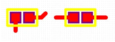
Solder mask, padstack, and thermal relief mistakes
Fine-pitch pads with minimal solder mask can create slivers and bridging risks. Inconsistently applied padstacks or inappropriate thermal reliefs complicate assembly and rework. Poor annular rings and nonfunctional pads can reduce yield and reliability.
How to avoid: Use consistent, library-controlled padstacks. Ensure adequate solder mask web and expansion for the assembly process. Prevent solder mask slivers and unintended openings. Apply appropriate thermal reliefs on copper pours feeding component pads to balance solderability and thermal performance.
-
Unbalanced copper and uncontrolled pours
Large copper pours added late in the design for "shielding" or aesthetics can trap noise, disrupt return paths, and create copper imbalance that leads to board warpage. Pour shapes without a defined tie to their reference can introduce unintended resonances.
How to avoid: Tie copper fills to a defined net and ensure continuity of return paths beneath high-speed traces. Use consistent pour rules and thermals. Balance copper density across the panel to mitigate warpage, and coordinate with the fabricator on etch compensation and plating effects.
-
Via-in-pad without proper filling or finish planning
Unfilled via-in-pad can wick solder, causing insufficient solder volume, voids, or tilt on fine-pitch parts. This leads to weak joints and assembly variability.
How to avoid: Plan via-in-pad technology with the assembler and fabricator. Use filled and capped vias where necessary and select appropriate finishes compatible with the assembly process. If via-in-pad is not essential, offset fanout to keep vias out of critical pads.
-
DFM/DFA mismatches and missing manufacturing guidance
Design rules that exceed fabrication capability, missing impedance callouts, incomplete fabrication notes, and lack of assembly constraints (e.g., reflow profiles, panelization guidance) drive delays, scrapped builds, and unexpected performance shifts.
How to avoid: Align design rules with actual fabrication and assembly capabilities. Provide complete fabrication and assembly notes, define critical dimensions and tolerances, and include test access requirements. Coordinate impedance coupons, stackup notes, and controlled processes so that the build reproduces the intended electrical performance.
Placement and Routing Practices That Prevent Rework
Preventing these mistakes starts with methodical placement and early constraint definition. Place clocks, memory interfaces, and high-speed transceivers to minimize route lengths and avoid plane crossings. Keep sensitive analog, RF, and high-impedance nodes isolated from high dI/dt regions. Distribute decoupling capacitors around major ICs with the shortest practical connection to power and ground references. During routing, reserve layers for specific functions: high-speed signals over continuous planes, noisy power switching regions confined and separated, and sensitive nodes shielded by grounded references.
For length-sensitive buses, manage timing through consistent topology and compact routing rather than extensive meanders. When meanders are unavoidable, distribute them and keep them within regions of consistent impedance and reference. Control the number of vias and ensure that each layer transition preserves a defined return path with stitching structures nearby.
Verification Before Fabrication
Constraint-driven design is complemented by verification. Validate rule coverage using design-rule checks targeted at plane crossings, impedance layers, diff-pair constraints, clearances, and copper pours. Perform focused signal and power integrity checks as needed: short channel simulations for reflections and terminations, decoupling impedance sweeps for PDN stability, and crosstalk checks for dense buses. Where available, use stackup calculators tied to actual dielectric data from the intended fabricator rather than generic values.
Finally, review fabrication and assembly documentation with the manufacturing partners. Confirm layer counts, materials, copper weights, impedance targets, tolerances, controlled processes, panelization, and test requirements. A brief pre-release review often prevents expensive, late-stage surprises.
In Summary
Most PCB design issues originate from gaps in stackup planning, return-path control, transmission-line awareness, power delivery design, and manufacturability alignment. By defining constraints early, maintaining continuous references, minimizing discontinuities, and coordinating closely with manufacturing, you can avoid these thirteen common mistakes and produce designs that are robust, buildable, and repeatable.