Introduction
Sequential lamination represents a critical manufacturing technique for producing high-performance HDI PCBs, particularly those with high layer counts, complex buildup structures, and dense interconnects. This process involves multiple lamination cycles to build dielectric and copper layers incrementally, enabling the integration of blind vias, buried vias, and microvias while maintaining precise layer alignment. Proper material selection plays a pivotal role in optimizing sequential lamination HDI PCB structures, as it directly affects thermal stability, signal integrity, dimensional control, and overall board reliability.
High-Tg PCB laminates emerge as a cornerstone for these processes, offering enhanced resistance to elevated temperatures encountered during multiple press cycles. Similarly, low Dk PCB materials sequential lamination ensures minimal signal loss in high-speed circuits. Addressing CTE mismatch PCB lamination remains essential to prevent mechanical stresses that arise from differential expansion between copper and dielectrics. By aligning material properties with process demands, manufacturers can produce boards that meet stringent performance criteria. Factory-driven insights reveal that consistent material behavior across cycles is non-negotiable for yield optimization.

How Sequential Lamination Builds Reliable HDI PCB Interconnect Structures
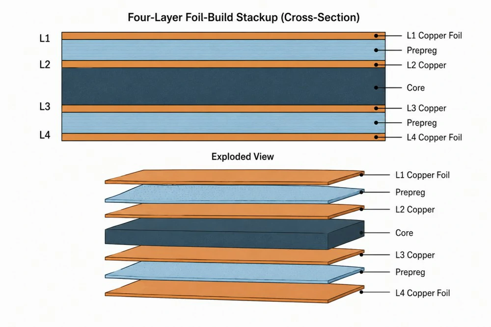
Sequential lamination refers to a multilayer PCB fabrication method where cores and prepregs are laminated in successive stages rather than a single cycle. For HDI PCB manufacturing, this approach accommodates the formation of blind vias, buried vias, and stacked or staggered microvias through progressive buildup layers. It is particularly useful when dense routing and compact interconnect structures require additional buildup layers around fine-pitch component footprints.
The relevance stems from the escalating demands of modern electronics for denser routing and faster signals. Traditional single-lamination struggles with thick stacks, leading to voids or incomplete fills. Sequential methods mitigate these by distributing thermal and pressure loads across cycles. However, they amplify material challenges, as each cycle exposes laminates to heat and pressure repeatedly. Poor selection exacerbates defects like via barrel cracking or board bowing. Industry practices emphasize materials engineered for multi-cycle stability to ensure long-term reliability in demanding environments.
The relevance of sequential lamination becomes more apparent as HDI designs require greater interconnect density within limited board dimensions. Each buildup cycle must maintain accurate registration between copper pads, dielectric layers, and laser-drilled microvias. Poor material stability or process control can therefore affect via alignment, dielectric thickness, and the reliability of the completed HDI interconnect structure.
Choosing Sequential Lamination PCB Materials for Thermal and Electrical Stability
Selecting sequential lamination PCB materials hinges on balancing thermal, mechanical, and electrical characteristics. Thermal properties govern stability during press cycles, where temperatures often exceed standard curing points. Dielectric attributes dictate signal propagation, vital for high-frequency performance. Mechanical resilience counters stresses from repeated processing. Engineers evaluate these holistically to avoid compromises in yield or functionality.
For sequential lamination HDI PCB structures, these properties become particularly important because microvia formation and fine-line routing leave less tolerance for dimensional variation. Material behavior must therefore remain predictable across multiple lamination and curing cycles.
Thermal Properties: Tg and CTE Considerations
Glass transition temperature, or Tg, marks the point where the laminate shifts from glassy to rubbery state, influencing flow and adhesion. High-Tg PCB laminates maintain rigidity at elevated temperatures, reducing resin flow inconsistencies across cycles. Coefficient of thermal expansion, CTE, measures dimensional change with heat, critical for multilayer harmony. Z-axis CTE, in particular, demands close matching to copper foil to avert cracks. Low Z-axis expansion materials prove ideal for sequential builds.
In HDI structures, low Z-axis CTE is especially relevant to microvia reliability because repeated thermal expansion can place stress on the plated copper inside small-diameter vias. When sequential buildup introduces multiple microvia layers, the cumulative effect of thermal cycling should be considered during material selection and stackup planning.

Dielectric Properties: Dk and Df
For a low loss HDI interconnect PCB, low Dk and low Df materials can support stable high-frequency transmission while allowing the sequential buildup structure to accommodate dense routing. These dielectric properties should be evaluated together with material thickness, copper roughness, and thermal stability. Maintaining consistent electrical properties after repeated lamination cycles is important for high-speed HDI interconnects where impedance and insertion loss must remain controlled.
Controlling CTE Mismatch During Sequential HDI PCB Lamination
CTE mismatch PCB lamination arises when dielectric and conductor expansions diverge, inducing shear stresses at interfaces. During cooling from lamination temperatures, higher CTE in resins relative to copper generates tensile forces on vias and pads. Repeated cycles compound this, risking delamination or microcracks. Factory monitoring focuses on symmetric stackups to symmetrize stresses. Material choices with tailored CTE profiles across X, Y, and Z axes distribute loads evenly.
This consideration becomes more critical in HDI PCB lamination because microvias, buried vias, and fine interlayer connections can be more sensitive to dimensional movement. CTE compatibility between the core, prepreg, copper, and buildup dielectric helps maintain registration and reduces mechanical stress around plated microvia structures during repeated thermal cycles.
IPC-6012 establishes performance benchmarks, including warpage tolerances that underscore CTE control. Prepreg-core combinations must exhibit compatible expansion to pass qualification. Process aids like carrier plates during pressing further stabilize dimensions. Engineers simulate thermal profiles to predict mismatch impacts pre-production.

How High-Tg Laminates Improve Sequential HDI PCB Reliability
High-Tg PCB laminates excel in sequential lamination by resisting softening during multiple heats. These materials sustain structural integrity, ensuring uniform prepreg flow without excessive squeeze-out. They also exhibit lower moisture absorption, minimizing voids from vaporization. Compatibility with lead-free profiles extends their utility in modern assembly. Selection involves verifying multi-cycle performance data from suppliers.
Pairing high-Tg cores with matching prepregs is particularly important in sequential lamination HDI PCB manufacturing because each additional buildup cycle introduces another thermal exposure. Stable resin systems can help maintain layer registration and dielectric thickness while supporting reliable microvia structures. For high-performance HDI PCBs, this material stability contributes to more consistent interlayer connections and reduces risks associated with repeated thermal processing.
Using Low Dk Materials in Low Loss HDI Interconnect PCB Structures
Low Dk PCB materials sequential lamination support high-frequency designs by reducing propagation delays. These resins, often with reinforced fillers, maintain low permittivity through thermal excursions. Challenges include higher costs and processing sensitivities, yet benefits outweigh for RF and data applications. Sequential builds can integrate low Dk materials into selected HDI layers to support high-speed routing and controlled signal paths. In compact low loss HDI interconnect PCB designs, material selection should be coordinated with layer thickness, impedance targets, copper distribution, and via transitions. This helps engineers balance routing density with the electrical requirements of high-speed interconnects.
Balancing low Dk with thermal stability requires hybrid stacks, blending standard and advanced materials judiciously. Df stability prevents skew in differential pairs. Factory validation confirms no degradation post-cycles.
HDI PCB Lamination Process Optimization: Materials, Stackup, and Press Control
Effective HDI PCB lamination process optimization demands rigorous material vetting aligned with the manufacturer's sequential buildup capabilities. Begin by defining performance requirements based on the end application, then evaluate high-Tg laminates for thermal stability, low Dk materials for high-speed signals, and compatible CTE characteristics for microvia reliability. Material and stackup trials should be completed before production to confirm dimensional stability across all lamination cycles.
- Evaluate resin flow and gel time for void-free bonds.
- Use symmetric constructions to counter bow and twist.
- Implement carrier-based pressing for thin cores.
- Monitor press parameters like ramp rates to avoid hotspots.
For HDI structures, process optimization should also consider microvia registration, buildup dielectric thickness, copper balance, sequential pressing conditions, and the relationship between each lamination cycle. These factors directly influence the quality of blind and buried vias and the consistency of high-density interconnect structures.
Resolving Warpage, Delamination, and Via Reliability Issues in Sequential HDI Builds
Warpage tops challenges in CTE mismatch PCB lamination, often from asymmetric builds or mismatched materials. Troubleshooting starts with stackup redesign for balance. Delamination signals excessive flow or contamination, addressed by plasma cleaning prepregs. Via failures trace to plating inconsistencies post-drilling.
Sequential processes amplify drill smear risks, mitigated by optimized feeds. Yield data guides iterative refinements. Standard-aligned practices ensure repeatability.
HDI-specific failures can also develop when sequential lamination cycles introduce registration variation between buildup layers. Microvias may miss their target pads, while excessive resin movement can affect dielectric thickness and via geometry. Troubleshooting should therefore examine the complete HDI stackup, including lamination movement, laser-drilled via position, copper distribution, and material behavior across repeated press cycles.
Conclusion
Optimizing sequential lamination HDI PCB structures requires coordinated control of material selection, stackup design, microvia formation, and repeated lamination cycles. High-Tg laminates provide thermal stability, low Dk materials support high-speed interconnect performance, and compatible CTE characteristics help reduce mechanical stress across buildup layers. Together, these factors contribute to reliable HDI structures with stable electrical and mechanical performance.
FAQ
Q1: What Is a Sequential Lamination HDI PCB?
A1: A sequential lamination HDI PCB is manufactured through multiple lamination cycles that progressively build dielectric and copper layers around a core structure. This approach supports blind and buried vias, stacked microvias, and dense interconnections that are difficult to achieve with a single lamination cycle. Material stability, layer registration, and process control are particularly important when multiple buildup stages are required.
Q2: How Does Sequential Lamination Improve HDI PCB Reliability?
A2: Sequential lamination distributes thermal and pressure exposure across multiple manufacturing stages, allowing complex HDI structures to be built progressively. Properly selected materials can maintain dimensional stability through repeated cycles, while controlled registration helps reduce interlayer misalignment. High-Tg laminates, compatible prepreg-core combinations, and suitable CTE characteristics can also help reduce risks such as delamination, warpage, and via-related failures.
Q3: What Materials Are Used for Sequential Lamination PCB Structures?
A3: Sequential lamination PCB structures typically require materials with stable thermal, mechanical, and dielectric properties. High-Tg laminates can withstand repeated thermal exposure, while low Dk and low Df materials may be selected for high-speed applications. Engineers should also evaluate CTE, resin flow, moisture absorption, and compatibility between cores and prepregs to maintain consistent performance throughout multiple lamination cycles.
Q4: How Does CTE Mismatch Affect Sequential HDI PCB Lamination?
A4: CTE mismatch during sequential HDI PCB lamination can create mechanical stresses because copper and dielectric materials expand and contract differently during thermal cycling. Repeated lamination cycles can increase the risk of warpage, delamination, or microcracks around vias and interfaces. Matching material expansion characteristics, maintaining a balanced stackup, and controlling pressing conditions can help reduce these reliability risks.
Q5: Why Are Low Dk Materials Important for Low Loss HDI Interconnect PCB Designs?
A5: Low Dk materials can help reduce propagation delay and support controlled electrical performance in high-frequency HDI structures. For a low loss HDI interconnect PCB, dielectric properties should remain stable after repeated thermal and lamination cycles. Engineers should evaluate both Dk and Df together with thermal stability, because low dielectric loss alone does not guarantee reliable performance throughout sequential PCB fabrication.
Q6: What Should Engineers Look for in a Sequential Lamination HDI PCB Manufacturer?
A6: Engineers should evaluate whether a sequential lamination HDI PCB manufacturer can control layer registration, material compatibility, pressing parameters, microvia formation, and multi-cycle dimensional stability. Manufacturing capability should also include appropriate inspection methods for warpage, delamination, via quality, and interlayer alignment. Reviewing actual process capability and material qualification data is important before selecting a supplier for complex HDI production.
Q7: How Can HDI PCB Lamination Process Optimization Improve Manufacturing Yield?
A7: HDI PCB lamination process optimization involves coordinating stackup construction, material selection, resin flow, CTE behavior, pressing temperature, pressure, and ramp rates. A balanced stackup can reduce warpage, while compatible materials help maintain stable dimensions through repeated cycles. Factory monitoring and post-lamination inspection can identify process variation early, helping improve consistency and reduce defects in sequential HDI production.
References
IPC-4101E — Specification for Base Materials for Rigid and Multilayer Printed Boards. IPC, 2010
IPC-6012E — Qualification and Performance Specification for Rigid Printed Boards. IPC, 2017
IPC-2221B — Generic Standard on Printed Board Design. IPC, 2012