When FR4 Still Wins and When an MCPCB Is the Thermal Tool
The FR4 vs metal core PCB decision is a heat-path decision, not a catalog preference. FR4 is the better manufacturing choice when heat is modest, spread across many parts, or can leave the board through copper planes, thermal vias, airflow, and a discrete sink. A metal core PCB (MCPCB / IMS) is the better choice when a few devices dump watts into a small pad and that heat must take a short vertical path through a thin dielectric into an aluminum or copper plate that bolts to a housing.
From a fabrication standpoint, most RFQs that fail this comparison either put multi-watt LEDs or FETs on 1.6 mm FR4 with no thermal vias, or they stamp "metal core" on a multilayer control board that still needs plated through-holes. We normally recommend FR4 for routing density and cost, and MCPCB when the metal plate is part of the product's heat sink. Copper-base MCPCB sits one step further: higher spreading than aluminum, higher board cost, and still the same dielectric as the real thermal bottleneck.

What Separates FR4 from MCPCB Before You Open a Quote
| Factor | FR4 PCB | Metal core PCB (MCPCB) |
|---|---|---|
| Bulk thermal conductivity | Laminate ~0.3 W/m·K | Dielectric typically 1–3 W/m·K (premium to ~8); Al base ~150–230 W/m·K; Cu base ~380–400 W/m·K |
| Useful thermal resistance | Set by via count, copper weight, and sink interface | Set mainly by dielectric thickness and W/m·K, then by plate-to-housing TIM |
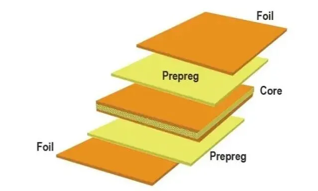
| Structure | Glass-epoxy core, 1–20+ layers, standard PTH | Foil + thin dielectric + metal plate; mostly 1 layer |
| High-power use | Works if heat is distributed or a discrete sink is designed in | Preferred when watts concentrate under a few packages |
| Electrical isolation | Bulk FR4 is the insulator | Only the dielectric isolates copper from the live metal plate |
| Manufacturing complexity | Any standard line | Special routing, limited PTH, dielectric and alloy must be named |
| Board cost vs FR4 | 1× baseline | Al MCPCB often ~2–4×; Cu-base higher; 2-layer IMS more again |
| Typical applications | Control, comms, mixed digital + modest power | LED modules, power stages, automotive lamps, motor drivers |
The FR4 vs MCPCB comparison that matters in CAM is not "0.3 versus 200 W/m·K." It is FR4 with a specified via farm and copper weight versus MCPCB with a named dielectric thickness, W/m·K, metal type, and working voltage. Quote packages that only say "metal core, 1.5 mm" get sent back.
Which Construction Wins When the Priority Changes
| If your priority is... | Better choice | Why |
|---|---|---|
| Lowest board cost and fastest prototype | FR4 | Stock laminate, standard process, any shop |
| Lowest junction temperature on a few hot pads | MCPCB | Short path through a thin dielectric into a metal spreader |
| Dense multilayer routing and PTH | FR4 | Metal core fights vias, inner layers, and controlled impedance |
| Highest heat spreading in the plate | Copper-base MCPCB | Copper conducts better than aluminum; dielectric still limits the first step |
| High isolation voltage | FR4, or thicker MCPCB dielectric | Thin high-W/m·K films trade voltage for heat |
| Mass production of mixed digital + modest power | FR4 + thermal vias / heavy copper | Cheaper than converting the whole board to IMS |
| LED or power stage bolted to a housing | Aluminum MCPCB | The plate is the heat-sink interface at a workable cost |
Why Thermal Conductivity Numbers Get Quoted the Wrong Way
A common FR4 vs metal core PCB comparison puts 0.3 W/m·K next to 200 W/m·K and stops. That number pair is incomplete. Heat leaving a pad on MCPCB must cross the dielectric first. In volume production that film is usually specified at 1.0, 1.5, 2.0, or 3.0 W/m·K, 75–150 µm thick. Premium grades go higher, but they cost more and are often thinner, which cuts breakdown voltage. The aluminum or copper plate then spreads heat sideways. If the plate never touches a sink or chassis, most of the metal advantage is wasted.
FR4 is a poor bulk conductor, but copper is not. A 2 oz plane plus a via farm under a pad can move a surprising amount of heat to the opposite side, where a sink or airflow sits. The trade-off is drill count, plating, and still a long path through glass-epoxy if anyone expects the laminate itself to carry watts. We see FR4 work on distributed 0.2–0.5 W parts and fail on a single 3–5 W LED with no copper pour and no vias.
Copper-base MCPCB does not erase the dielectric. It only improves spreading after heat has already crossed that film. From a fabrication standpoint, specify dielectric W/m·K and thickness on MCPCB the same way you specify Tg and copper weight on FR4. "Metal core, good heat dissipation" is not a stack-up.

Thermal Resistance Is the Number That Actually Moves Junction Temperature
Conductivity is a material property. Thermal resistance is what the part feels. On MCPCB, Rθ from pad to plate is roughly dielectric thickness divided by (conductivity × pad area). Halve the thickness or double the W/m·K and Rθ drops in proportion — until isolation voltage or pinhole risk stops you. That is why a 75 µm / 3 W/m·K film can beat a 150 µm / 1 W/m·K film on heat and lose on hipot.
On FR4, Rθ is not a single film. It is the parallel path of copper pour, plated vias, residual glass-epoxy, and the sink interface. CAM can add vias and copper, but we cannot invent a short path if the layout left a thermal pad sitting on soldermask over 1.6 mm of laminate. In production we typically recommend via diameter, plating thickness, and a keep-out so the pad does not starve of copper. The FR4 vs MCPCB performance comparison should be run as Rθ-pad-to-ambient in the real housing, not as two conductivity numbers from a brochure.
This becomes noticeable during design review when someone models MCPCB with the aluminum conductivity and ignores TIM plus housing convection. The plate is only as good as the interface behind it. Bare aluminum oxidizes and is not optically flat. If the customer expects the raw plate to replace a machined sink without TIM, junction temperature will miss the model. We flag that during DFM the same way we flag missing via-in-pad on FR4 power footprints.
How the Stack Itself Limits Routing and Isolation
FR4 is an insulator that happens to hold copper. You can stack layers, plate holes, and treat creepage as a layout problem until voltage gets extreme. An MCPCB is a conductor with a thin coating. Isolation voltage is set by dielectric thickness, filler, pinholes, and edge distance. A 75 µm high-conductivity film that looks excellent on a thermal plot may only be comfortable at low voltage. A 150 µm mid-grade film trades some heat for a more honest hipot result.
Layer count is the structural limit that kills more metal-core RFQs than conductivity. Most production MCPCB is single-sided. Two-layer IMS exists, but the extra insulation and the need to isolate vias through the metal raise cost and drop yield. Dense thermal-via fields copied from an FR4 library are the wrong geometry: each isolated hole removes metal and interrupts the spreader. We normally keep power on single-sided MCPCB and move control circuits to a separate FR4 board rather than force insulated PTH through aluminum or copper.
Mechanically the plate is useful. LED bars stay flat, power modules do not oil-can in the housing, and warp after reflow is usually lower than a large thin FR4 panel. The cost is weight, limited outline options, and machining. Routing aluminum or copper needs different feeds than glass-epoxy. Small holes in the metal are slow. CTE mismatch is the reliability item after heat: aluminum expands more than copper foil and far more than a ceramic LED package. The dielectric has to absorb that strain through reflow and field cycling. Cheap dielectric plus large ceramic packages is a solder-joint and pad-lift risk. FR4 is not innocent — it warps and its Z-CTE hammers vias — but those failure modes are known on every line.
Where High Power Actually Forces a Metal Core
High power in this comparison means concentrated watts per square centimeter, not a large board that dissipates 20 W across 200 cm². Street-lamp COB modules, automotive headlamp strings, compact half-bridges, and LED engine plates are the jobs where MCPCB earns its keep. The heat path is short, the schematic is simple, and the housing is already metal. FR4 with heavy copper and vias can still serve distributed power — POL converters, many mid-power FETs with copper pours, or a TO-package sitting on a discrete sink.
The wrong high-power call is converting an entire mixed board to metal core because one regulator runs warm. That raises application cost, kills routing, and often does not drop the hot-spot temperature if the plate has no thermal exit. The right high-power call is putting the hot devices on MCPCB and leaving the MCU, connectors, and isolated supplies on FR4. Most PCB manufacturers will recommend that split before they recommend 2-layer IMS with insulated vias through the plate.
Copper-base MCPCB shows up when aluminum dielectric-plus-plate still leaves the junction too hot and the layout remains simple. It is not the default FR4 vs MCPCB answer. It machines worse, costs more, and still lives or dies on the same dielectric and TIM.
Where Application Cost Starts to Diverge from Board Price
Board price is the easy number. Simple 1-layer aluminum MCPCB often lands around 2–4× a comparable FR4 board. Copper-base and 2-layer constructions move higher. Panel utilization is worse: metal sheets are heavier, scoring is limited, and many outlines are milled in small arrays. That labor shows up even when the metal itself is not exotic.
Application cost can still favor MCPCB. If the plate replaces a machined sink, cuts LED or FET derating, and removes a thermal-via farm plus extra copper weight on FR4, system cost may fall even while the bare board is more expensive. The opposite is also common: specifying MCPCB for a control board adds metal machining, hipot-to-plate test, mounting-hole insulation, and a connector to a daughter card the design did not budget. We normally quote both constructions against the same housing before anyone locks the mechanical drawing.
Lead time follows process familiarity. FR4 is stocked on every line. MCPCB dielectric grades are stocked in the common 1–3 W/m·K band; premium films and copper base add days. Brand-locked dielectric is the usual schedule risk, not the aluminum sheet.
What CAM and the Floor Check Before Either Stack Is Released
During CAM review we look at watt density first, then layer count. A 1-layer LED drawing with large copper pours and a named 2.0 W/m·K dielectric is a clean MCPCB job. A 4-layer gerber stamped "please use metal core for heat" is not. Process stability on FR4 is higher because every line already runs it. MCPCB needs controlled dielectric press, metal routing, and careful outline quality so the thin insulation is not cracked at the edge.
Inspection differs. FR4 gets standard electrical test plus impedance if specified. MCPCB adds hipot to the plate, peel on the dielectric, and flatness. Yield tends to decrease when isolated PTH is required: each hole is an insulation feature, not just a drill. Mounting holes through the metal need insulation or an isolating shoulder; otherwise the screw shorts the plate to a circuit or to earth in a way the designer did not intend. Most PCB manufacturers will ask for working voltage before locking dielectric thickness. If that number is missing, we default conservative and thermal resistance goes up.
We normally recommend FR4 when thermal vias and copper can meet the rise. We recommend aluminum MCPCB when the plate is part of the product's heat sink and the circuit fits on one or two layers. We recommend copper-base only after aluminum with a real dielectric spec still misses the junction target. We recommend against mixing a high-W/m·K marketing number with an unspecified voltage and a via-in-pad farm copied from an FR4 library.
Pick the Construction That Matches the Heat Path
Choose FR4 if you:
- Need more than one or two signal layers, or plated through-holes as a normal interconnect.
- Can keep junction temperature in range with copper weight, thermal vias, airflow, or a discrete sink.
- Want the lowest board cost, shortest lead time, and any qualified shop.
- Need bulk electrical insulation without betting on a 75–150 µm film.
- Are running mixed digital and modest power on the same outline.
Choose a metal core PCB if you:
- Have concentrated watts (LEDs, FETs, regulators) on a simple copper layer.
- Can bolt or bond the metal back to a housing or sink with a real TIM.
- Will name dielectric thickness, W/m·K, metal type, and working voltage on the drawing.
- Accept roughly 2–4× board cost (more for copper base) and more limited machining versus FR4.
- Do not need a dense via field through the metal.
Split the product if you:
- Have a hot power stage and a busy control section on one schematic.
- Would otherwise force 2-layer insulated vias through the metal plate.
- Can accept a connector or solder joint between an MCPCB power plate and an FR4 controller.
There is no single winner in the FR4 vs metal core PCB comparison. The better thermal construction is the one whose heat path exists in the finished assembly, not only in the laminate table.
Questions That Show Up on FR4 and MCPCB RFQs
Q1: Is a metal core PCB always better than FR4 for thermal management?
A1: Only when heat can cross a thin dielectric into a metal plate that actually rejects heat. If the plate hangs in air, or the circuit needs four layers of PTH, FR4 with copper and vias is often cooler at the system level and cheaper to build.
Q2: What dielectric W/m·K should I specify on an MCPCB?
A2: Volume lighting and modest power usually start at 1.0–2.0 W/m·K and 75–100 µm. Move to 2.0–3.0 W/m·K when pad temperature is still high. Higher grades help, but check breakdown voltage before you thin the film.
Q3: Aluminum MCPCB or copper-base MCPCB?
A3: Aluminum is the production default. Copper-base improves spreading after the dielectric and costs more to buy and machine. Use it when a named aluminum stack still misses junction temperature and the layout stays simple.
Q4: Can I copy an FR4 thermal-via footprint onto MCPCB?
A4: Usually no. Vias through the metal must be isolated, the isolation drill removes spreader area, and dense via farms weaken the plate. On single-sided MCPCB the heat path is down through the dielectric, not through a via array. Redesign the pad as a copper pour over intact metal.
Q5: How much more does an MCPCB cost than FR4?
A5: Simple 1-layer aluminum MCPCB is often about 2–4× a comparable FR4 board. Copper-base and 2-layer IMS cost more. System cost can still fall if the plate replaces a sink and cuts device failures. Quote both constructions before locking the housing.
Q6: When should power stay on MCPCB and control stay on FR4?
A6: When the hot devices want a metal plate and the rest of the schematic wants vias, connectors, and inner layers. That split is usually higher yield than forcing the entire product onto 2-layer IMS.