Replacing a Fuse with a PCB Trace: Technically Possible, Poor Practice
In electronics, cost reduction is a constant theme. Engineers have used many unconventional methods to save a few cents. Using PCB traces as antennas is already a familiar practice: a carefully shaped copper feature takes on signal reception, simplifies the bill of materials, and removes the cost of a discrete antenna. That approach is used on many real products.
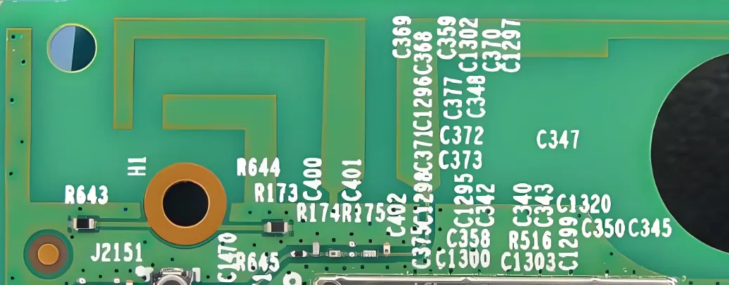
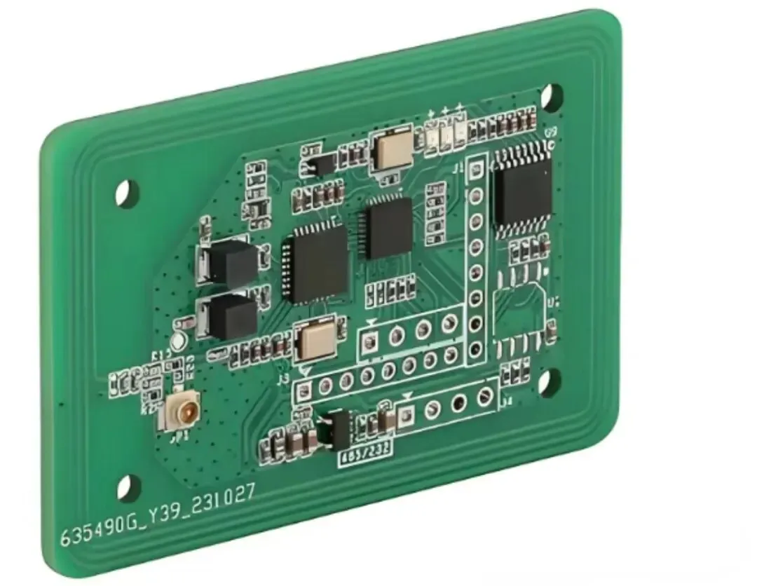
A more recent idea is far more surprising: using a PCB trace to replace a fuse. The part that is supposed to open under overload and protect the circuit would be replaced by a copper-foil trace. The question is whether this is a clever cost-saving method or a gamble with safety.
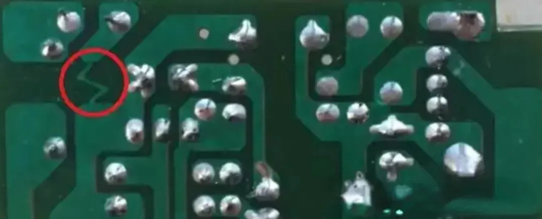
The conclusion first: it is technically feasible, but it is not recommended in practice.
How a Copper Trace Can Act as a Fuse
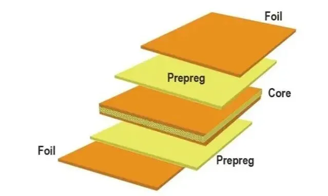
The core idea of replacing a fuse with a PCB trace is straightforward. Use the current-carrying limit of copper foil. By controlling trace width, length, and thickness, the trace operates at rated current without opening. When the circuit is overloaded and the current exceeds what the copper can withstand, the trace overheats and opens, interrupting the circuit.
A common PCB copper thickness is 35 μm. At a trace width of 1 mm, copper foil of this thickness can carry about 1 A per millimeter of width. If the circuit needs 5 A protection, a 5 mm-wide trace would theoretically be sufficient. In practice, length and heat dissipation must also be taken into account. Dedicated calculation tools are used in the industry to set the required parameters. For a target current of 10 A, for example, the required via count and temperature rise can be calculated explicitly.
That calculation is what makes the method look attractive on a schematic review. Copper is already on the board. If width and thickness can be chosen so the foil opens at a chosen current, a discrete fuse footprint disappears. The electrical idea is the same idea that already limits every power trace: copper has finite ampacity, and excess current turns into heat until the conductor fails.
A fuse, however, is not only a conductor that eventually melts. It is a component whose opening time, clearing behavior, and failure mode are specified. A PCB trace can be sized to heat up. It does not automatically inherit those specified behaviors.
Critical Risks That Cost Reduction Should Not Ignore
Although the method is technically possible, replacing a fuse with a PCB trace introduces hazards that cannot be designed away by tightening width alone. These five risks cannot be bypassed.
After it opens, the board is scrap
A standard fuse can be replaced after it opens, at low cost and with little effort. After a PCB trace fuses, it cannot be replaced on its own. The open is a burned gap in the laminate and copper. Repair means cutting, jumpering, or replacing the PCB. Maintenance cost rises and material is wasted.
That difference matters as soon as the product leaves a disposable prototype. Field service that would have been a fuse swap becomes a board swap. The cents saved on the first build are spent again every time the protection actually works.
Fire and secondary short circuits
Safety risk is high. When the trace opens, copper foil may splash metal balls and cause a secondary short. If the copper foil is designed incorrectly, too long or too short, it may fail to open in time and allow the input wiring to overheat and catch fire, or it may carbonize the PCB and damage nearby components.
A fuse body is built to contain the opening event. An open copper trace is not. The energy that melts the foil is released on the laminate, next to other nets, soldermask, and components. Carbonized resin can become a leakage path. Spattered copper can bridge lands that were never part of the protected net. The protection event then creates a second fault.
Fusing behavior cannot be controlled reliably
A standard fuse can be specified for fast-blow or slow-blow operation. Opening time is part of the part number. A PCB trace has only copper foil as the material, so response speed and consistency are poor. It may fail to open when it should, or open when it should not.
Ambient temperature, nearby copper pours, airflow, and whether the trace sits over a plane all change how fast the foil heats. Two boards from the same panel can open at different currents if etching tolerance or stack-up heat spreading differs. That scatter is the opposite of what overload protection is supposed to provide.
Safety approval is unlikely
Exposed copper foil is easily affected by electrostatic discharge, moisture, and temperature variation, so stability is poor. Safety standards in many countries and regions, for household appliances and automotive electronics, for example, either prohibit this design or restrict it tightly. The design is unlikely to pass review.
A product that cannot be approved cannot be sold in those markets. The fuse cost that was removed is then small compared with a failed certification or a restricted application list. Trace-as-fuse cost reduction only exists in markets and product classes that never ask how the input is protected.
Design difficulty can erase the savings
Drawing a trace is not enough. To obtain a usable fusing result, the parameters must be calculated precisely. A single-bend trace should be used rather than a serpentine trace, in order to reduce the effect of heat dissipation. A meander adds copper area and couples the hot segment to nearby copper, so the foil may run cooler than the calculation assumed and fail to open.
Manufacturing tolerance requirements are extremely tight. A small error in width, copper thickness, or residual copper after etch can make the protection ineffective and raise production cost instead. The layout then needs extra review, extra process control, and extra explanation to the fabricator, effort that a catalog fuse does not require.
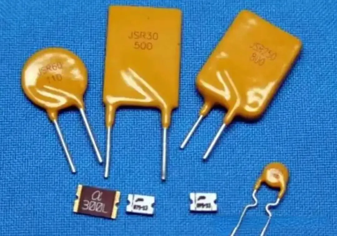
Standard fuses, by contrast, are available in many ratings for different applications. Common types such as JSR30 and SR60 are established, safety-oriented choices with defined ratings and replaceable bodies.
Cost Reduction Must Not Cross the Safety Line
Saving the cost of one fuse means accepting risks such as board scrap, safety incidents, and failed safety approval. Those losses far exceed the cost that was saved.
Using a PCB trace as an antenna is a different class of decision. An antenna trace that performs poorly is usually an RF or range problem. A protection trace that performs poorly is a fire, a secondary short, or an un-serviceable board. The two cost-saving ideas should not be treated as equivalent just because both replace a purchased part with copper.
Whether the product is a household appliance, an automotive electronic system, or industrial equipment, a standard fuse is the more reliable choice. It meets safety standards, provides defined protection, and is easy to service later. The core of electronic design is reliability and safety. Cutting cost while ignoring these risks will cost more in the end.