Introduction
In the PCB manufacturing process, bare board testing serves as a critical gatekeeper before components are populated. This stage verifies the electrical integrity of unpopulated printed circuit boards, identifying defects such as opens, shorts, and improper connections that could lead to assembly failures or field returns. Electric engineers rely on these tests to ensure that the foundational wiring matches the design netlist precisely, minimizing risks in high-density, multilayer boards. Common bare board test methods include PCB continuity testing and PCB isolation testing, which form the backbone of quality control in factories. By catching issues early, manufacturers avoid the exponential costs associated with rework after soldering. Ultimately, robust bare board testing aligns production with reliability demands in demanding applications like aerospace and telecommunications.
What Is Bare Board PCB Testing and Why It Matters
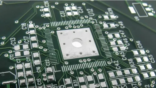
Bare board PCB testing involves systematic electrical verification of printed boards without components, focusing on the copper traces, vias, and planes. Factory processes generate a test program from the design netlist, which maps all electrical networks, allowing automated equipment to probe points and confirm connectivity. This testing confirms that manufacturing steps like etching, plating, and drilling have produced a board true to specifications. Without it, subtle defects propagate to assembly, causing yield losses that strain production timelines.
The relevance stems from the complexity of modern PCBs, where multilayer stacks and fine-pitch features amplify defect risks. A single open in a power net or short between signal lines can render an entire assembly nonfunctional, leading to scrapped materials and delayed shipments. In high-volume factories, bare board testing achieves test coverage exceeding 90-100% for accessible nets, directly impacting overall equipment effectiveness. For electric engineers specifying boards, insisting on this step ensures compliance with performance expectations under operational stresses like thermal cycling.
Core Principles of Bare Board Test Methods
Bare board test methods primarily revolve around verifying electrical paths through resistance, capacitance, or vector-based measurements. PCB continuity testing applies a low-voltage stimulus to each net, measuring resistance to detect opens where paths exceed thresholds, typically in the megaohm range or higher indicating failure. Conversely, PCB isolation testing stresses adjacent nets with voltage differentials, checking for leakage currents or shorts below minimum resistance values. These methods use the netlist to sequence probes across thousands of points, ensuring comprehensive coverage.
Open short test PCB combines these into a single program, first charging nets capacitively to flag anomalies quickly, then refining with DC resistance for precision. Capacitance testing excels for high-speed detection on dense boards, as it induces charges without physical contact wear. Engineers appreciate how these principles scale from prototypes to production, adapting to board sizes up to 24x24 inches.
As outlined in IPC-9252, continuity must register below 10 ohms for Class 3 boards, providing a standardized benchmark for factory acceptance.
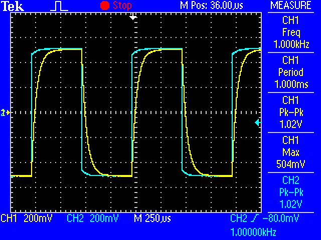
Resistance-based approaches dominate for accuracy, applying currents from microamps to milliamps while monitoring voltage drops per Ohm's law. Isolation often employs guarded measurements to eliminate stray capacitance influences, crucial for high-impedance nets. Vectorless testing supplements where probe access limits, using time-domain reflectometry for via integrity.
Bare Board Testing Equipment Overview
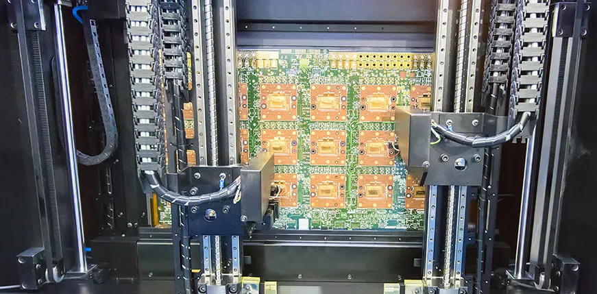
Factories deploy specialized bare board testing equipment tailored to volume and complexity. Flying probe systems use 2-8 independent probes that move via linear motors, contacting pads at speeds up to 150 points per second without custom fixtures. This flexibility suits low-to-medium volumes and double-sided boards, enabling quick program generation from netlists.
Bed-of-nails fixtures, or dedicated clamshell testers, press hundreds of spring-loaded pins against test points simultaneously, achieving throughputs over 100 boards per hour for high-volume runs. Universal grid systems offer a compromise, using interchangeable receiver fixtures on a common bed for faster changeovers. Selection hinges on net count, pitch down to 0.15mm, and multilayer depth.
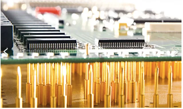
Advanced equipment integrates software for fault diagnosis, highlighting defect locations on Gerber overlays for repair routing. Probe force calibration to 50-150 grams prevents board damage, while vacuum hold-down ensures planarity during testing. Electric engineers value equipment logging test data for traceability, supporting failure mode analysis.
Flying Probe vs Fixture-Based Bare Board Testing Machines
Bare board testing machines fall into two production classes: fixtureless flying-probe systems and fixture-based testers (dedicated bed-of-nails or universal-grid). Both execute the same electrical checks against a netlist. They differ in how they make contact, how fast they run, and when the capital cost pays back.
| Factor | Flying probe | Fixture-based (bed-of-nails / grid) |
|---|---|---|
| Contact method | 2–8 moving probes, sequential | Hundreds to thousands of spring pins, parallel |
| Typical cycle time | 30 s to 15 min per board (net-count dependent) | 3–40 s per board (almost independent of net count) |
| Fixture NRE | None | Typically hundreds to several thousand dollars per design; complex double-sided fixtures can exceed that |
| Fixture lead time | Hours for program generation | Days to weeks for pin plate, wiring, and debug |
| Design-change impact | Recompile from CAM/netlist | New or modified fixture |
| Fine-pitch access | Strong; many systems probe pads well below 0.2 mm | Limited by pin pitch and pad size; fine-pitch pins cost more and wear faster |
| Best fit | Prototypes, NPI, high mix, frequent ECOs | Frozen designs, high volume, stable test-point layout |
Engineering rule of thumb: use flying probe while the design is still changing and lot sizes stay in the tens to low hundreds. Move to a fixture when test time, not programming time, becomes the constraint—usually once the same part number repeats at production volume and the test-point map is frozen.
Do not treat the two classes as mutually exclusive. Many factories keep a flying-probe machine for first articles, ECO lots, and boards that cannot accept a fixture (very fine pitch, missing test pads, flex that will not sit flat on a pin field) and reserve fixture testers for the high-runners.
How to Choose a Bare Board Testing Machine
Specify the machine from the board and the line, not from a brochure speed claim.
1. Volume and mix
- Low volume / high mix / frequent revisions → flying probe, preferably double-sided.
- Medium volume with several live part numbers → automated flying probe or a universal-grid system with interchangeable receivers.
- High volume, few part numbers → dedicated fixture tester with loader/unloader.
2. Net count and adjacency A 500-net prototype and a 10,000-net HDI panel do not belong on the same utilization model. Flying-probe time scales with nets and with how many isolation pairs you require. Fixture time stays nearly flat because all pins are already down. If IPC-9252 adjacency or high-voltage isolation across many net pairs is mandatory, fixture or grid systems finish that work far faster.
3. Pitch, pad size, and stack-up Ask vendors for minimum reliable pad diameter and pitch on your finish (OSP, ENIG, immersion silver), not only the catalog minimum. Soft-touch or low-force probes matter on gold bond pads and thin flex. Buried and blind vias need double-sided access or a fixture strategy that still reaches both ends of the net.
4. Board mechanics Thin cores, flex, rigid-flex, and large panels warp. Vacuum tables, stretch frames, and thickness-aware camera Z-axes reduce false opens. Ceramic and LTCC need controlled probe force and often a horizontal architecture.
5. Measurement set If the line only needs open/short against a netlist, a basic flying probe is enough. If you must qualify via plating with milliohm readings, catch latent leakage, or run hipot on power nets, the machine must support those modes natively—not as a later "software option" that the hardware cannot actually drive.
6. Factory constraints Footprint, operator skill, SMEMA in-line space, fixture storage, and CAM bandwidth often decide the purchase before raw test speed does. A vertical flying probe that one technician can load in a tight room can beat a faster horizontal line that nobody can staff on third shift.
Common purchasing mistakes
- Buying a fixture tester before the test-point map is frozen, then scrapping the fixture after an ECO.
- Specifying flying probe for a 10,000-unit consumer run because "no fixture cost" looked cheaper on the quote; test hours erase that saving.
- Ignoring probe-mark limits on RF pads and wire-bond pads.
- Accepting "100% coverage" without asking whether isolation is adjacent-nets only or full net-to-net.
4-Probe vs 8-Probe and Vertical vs Horizontal Architectures
Probe count and frame orientation are the two architecture choices that most affect throughput and floor layout.
Probe count
- 4 probes (typically 2+2 or 4 on one side): lower capital cost, adequate for prototypes, inner layers, and modest net counts. Isolation and four-wire work are slower because fewer heads can sit on a net at once.
- 8 probes (typically 4+4): higher points-per-second, better for dense double-sided boards, and more room to run Kelvin or multi-point continuity without extra moves. The extra heads help most when both sides must be probed and when capacitance screening and DC verify run in the same program.
More heads do not help if the CAM program is poorly optimized or if the board has few accessible pads. Software path planning matters as much as head count.
Orientation
- Vertical systems: small footprint, easy manual load/unload, good for labs, job shops, and high-mix cells. Panel size and automation options are more limited.
- Horizontal systems: natural fit for conveyors, dual-sided access at production speed, and in-line cells. They take more floor space and are the usual choice once unattended running is required.
Single-sided vs double-sided Single-sided machines miss nets that only break out on the opposite face—common on HDI and boards with blind vias. For multilayer production work, specify dual-sided probing or a dual-well fixture. Soft-touch and camera-guided alignment should be mandatory below about 0.2 mm pad pitch.
Advanced Measurement Modes on Bare Board Testers
Open/short against a netlist is the baseline. Production-grade bare board testing machines add modes that catch defects a simple resistance scan will pass.
Kelvin / 4-wire resistance
Used for via barrels, plated through-holes, and narrow copper that must stay in the milliohm-to-low-ohm range. Two-wire continuity can hide thin plating because lead and contact resistance swamp the defect. Specify 4-wire when Class 3 via integrity or power-net resistance is a customer requirement.
High-voltage isolation / hipot
Raises the stress between nets (often tens to a few hundred volts, sometimes higher on power or safety-isolated designs) and measures leakage. This finds contamination, incomplete etch, and hairline copper that pass a low-voltage short test and fail later under bias. Match voltage and dwell to the dielectric and creepage of the design; over-voltage on thin HDI dielectrics creates its own damage.
Latent-defect and micro-short inspection
Looks for intermittent or high-impedance paths that are not a hard short. Typical implementations combine elevated voltage, sensitive current measurement, and sometimes capacitance or time-based signatures. These modes matter on HDI, mSAP, and substrate work, where etch residue and micro-bridges are the dominant escape risk.
Guarded and high-impedance isolation
Needed when nets sit next to planes or when stray capacitance would make a raw isolation reading look like a leak. Guarding is a machine and fixture-wiring capability, not only a software checkbox.
Embedded passive / inner-layer extras
Some testers can measure embedded resistors or capacitors and check inner layers before lamination. Use this only if the stack-up actually contains those features; it is not a substitute for finished-board netlist test.
Program these modes onto the nets that need them. Running hipot and 4-wire on every net inflates cycle time without improving escape rate on ordinary signal traces.
Throughput, Fixture Cost, and Total Cost of Test
Evaluate bare board testing machines on cost per good board, not list price.
Throughput drivers
- Flying probe: points per second (often tens to low hundreds), number of heads, travel optimization, and whether capacitance pre-screen reduces DC moves.
- Fixture tester: clamp/unclamp time, scanner speed, and loader cadence. Once pins are down, adding nets barely changes the cycle.
Published points-per-second figures assume short moves and easy pads. Fine pitch, dual-sided targeting, Kelvin moves, and HV dwell cut real throughput sharply. Ask for a timed program on a board that matches your net count and pitch.
Cost model to run before purchase
| Cost element | Flying probe | Fixture-based |
|---|---|---|
| Machine capital | Higher for a given throughput | Often lower for raw boards/hour; fixture inventory is extra |
| Per-design NRE | Program only | Fixture build, debug, spare pins |
| Per-board test time cost | Rises with nets | Nearly flat |
| Changeover | Minutes | Fixture swap plus first-article check |
| Hidden cost | Probe tips, calibration, longer queue time | Fixture storage, pin replacement, ECO scrap |
A practical crossover: when fixture NRE plus a few seconds of test labor per board undercuts minutes of flying-probe time across the expected lifetime volume of that part number, move the job. Complex boards hit that point sooner because flying-probe time grows with nets while fixture time does not.
Reliability note
Cheaper contact that marks pads, skips small vias, or uses worn pins produces false passes. Those escapes cost more than a slower, better-controlled test. Budget tip replacement and daily verification coupons in the TCO, not only the machine invoice.
Fine-Pitch, HDI, Flex, and Substrate Testing Capability
Machine capability for dense and non-rigid boards is a specification block, not a marketing adjective.
What to put on the RFQ
- Minimum pad diameter and pitch with the probe type you will actually run
- Positioning repeatability (a few micrometers on substrate-class machines)
- Maximum panel size and thickness range
- Dual-sided access and camera alignment on both sides
- Vacuum or stretch-frame hold-down for flex and thin cores
- Temperature stability if capacitance or high-impedance isolation is used on large panels
HDI and IC-substrate work often needs pitches in the tens of micrometers and controlled force so pads are not cratered. Flex and rigid-flex need planarization; a warped panel creates false opens that look like plating voids. Universal-grid and dedicated fixtures struggle first on pitch; flying probes struggle first on time. For mixed technology (rigid plus flex tail), confirm the machine can support the tail without over-probing the stiffener or connector area.
If the product uses mSAP, SLP, or package substrates, treat capacitance scanning and latent-defect modes as part of the base machine, not optional extras.
Manual, Semi-Automatic, and In-Line Automated Testers
Loading method should match labor cost and lot size.
- Manual: operator places the board, starts the program, sorts pass/fail. Lowest automation cost. Best for prototypes, repairs, and low volume. Throughput is gated by handling, not by the measurement engine.
- Semi-automatic: vacuum table, cameras, and guided loading reduce alignment error. Useful when boards are thin or operators rotate.
- In-line / fully automatic: SMEMA-compatible conveyors or stack loaders, auto pass/fail sorting, optional 24-hour unattended runs. Required when flying probe is asked to cover mid-volume production without fixtures.
Automation does not fix a weak program. It multiplies whatever coverage and false-call rate you already have. Before adding a loader, lock CAM-to-netlist correlation, probe-force limits, and fail-map review so the cell does not automatically stack bad boards into the good lane.
For fixture lines, automation is usually easier because cycle time is short and the board location is fixed. For flying probe, automation pays off only after path time is already optimized.
Capacitance Screening vs Resistance Verification on Production Machines
On a production tester these are two stages, not two philosophies.
Capacitance (and related vectorless or charge-based screens) finds missing copper, unexpected coupling, and many opens/shorts without dwelling on every net pair with DC. It is fast and easy on the probes. It is also less specific: a capacitance miss still needs a location and a pass/fail rule tied to a known-good or calculated model.
Resistance/DC continuity and isolation remain the acceptance measurements that map to IPC-style thresholds. Kelvin DC is what you use when plating thickness or via integrity is the question.
Practical program structure
- Capacitance or charge screen across the panel to flag outlier nets quickly.
- DC continuity and isolation only on flagged nets plus critical nets (power, high-speed, safety isolation).
- 4-wire or hipot only where the design requires it.
That sequence is how factories raise points-per-hour without lowering the electrical standard. Using capacitance alone as the ship criterion is a process risk on Class 3, automotive, and aerospace boards. Using DC alone on every net pair of a dense HDI panel wastes machine time that a screen-then-verify program would recover.
Practical Best Practices in Factory Implementation
Implement bare board testing post-final fabrication, after solder mask and silkscreen, to capture all process-induced defects. Verify netlist integrity against CAM data before programming, resolving discrepancies to avoid false calls. Aim for 100% net coverage, prioritizing high-speed signals and power planes first in test sequences.
Calibrate equipment daily per manufacturer guidelines, monitoring probe tip wear and fixture alignment. Segregate boards by class, applying IPC-6012 performance criteria for qualification lots. Document reject rates, targeting under 1% for mature processes, and feed data back to upstream etching controls.
Incorporate environmental controls, testing at 23°C and 50% RH to mimic assembly conditions. For HDI boards, combine flying probe with boundary scan prep for hybrid coverage.
Troubleshooting Common Bare Board Test Failures
Open failures often trace to drill breakout or plating voids, inspect vias microscopically for barrel integrity.Shorts arise from etch residue or mask misalignment, requiring plasma cleaning validation.False opens from probe misalignment demand fixture redesign with taller pins.Capacitance anomalies signal delamination; cross-section suspect nets.High continuity resistance flags thin plating; measure coupon resistances from panels.
Conclusion
Bare board PCB testing fortifies PCB reliability through meticulous continuity and isolation checks using proven equipment and methods. Adhering to standards like IPC-9252 ensures factory outputs meet engineering demands. Prioritizing these practices yields defect-free foundations for assembly success.
FAQ
Q1: What is a bare board tester?
A1: A bare board tester is an electrical test machine that checks an unpopulated PCB for opens, shorts, and netlist errors before components are mounted. Bare board testing machines contact pads, vias, and planes with flying probes or a pin fixture, then compare measured continuity and isolation with the design netlist. They do not verify soldered parts, polarity, or powered function. That work belongs to ICT, flying-probe ICT, or functional test after assembly. Used at fabrication, the tester stops plating voids, etch bridges, and drill errors from entering SMT.
Q2: Do flying probe bare board testers need a custom fixture?
A2: No. A flying-probe bare board testing machine holds the panel in a generic table or conveyor and moves 2–8 probes to each test point under software control. The program comes from Gerber and netlist data, so a new part number does not need a dedicated pin plate. Fixture-based machines still need a bed-of-nails or grid receiver for parallel contact. Choose flying probe when designs change often or volumes are too low to recover fixture NRE; choose a fixture when cycle time, not setup time, limits the line.
Q3: What is the difference between a bare board tester and ICT?
A3: A bare board tester measures copper connectivity on an unpopulated board: opens, shorts, isolation, and sometimes via resistance. ICT (in-circuit test) runs after assembly and checks mounted components, joints, and often limited powered measurements through a bed of nails or flying probes. The same mechanical idea—flying probe versus fixture—appears in both stages, but the defect set is different. Bare-board electrical test will not catch a wrong resistor value or a BGA solder void. ICT will not reliably find an inner-layer etch short that was already covered by parts. Most production flows need both.
Q4: How much do bare board testing machines cost?
A4: Purchase price depends on class. Compact fixture-based electrical testers and basic BBT cells can start in the tens of thousands of dollars. Production flying-probe bare board testers commonly fall in the high-tens to several-hundred-thousand-dollar range, depending on probe count, dual-sided access, and automation. Fully integrated in-line cells with loaders cost more. Separate from the machine is fixture NRE on bed-of-nails systems, often hundreds to several thousand dollars per design. Compare cost per good board over expected volume, not list price alone.
Q5: How long does a flying probe test take on a bare board?
A5: Typical flying-probe cycle time is about 30 seconds to 15 minutes per board. Time scales with net count, whether both sides are probed, and whether the program runs only adjacent isolation or also Kelvin and high-voltage dwell. Fixture-based bare board testing machines usually finish in a few seconds to under a minute because all pins contact at once. Published points-per-second figures assume short moves and easy pads; fine-pitch HDI and hipot steps are slower. Ask the vendor to time a program on a board that matches your net count and pitch.
Q6: What files are required to program a bare board testing machine?
A6: The tester needs a netlist plus board geometry. Fabricators typically supply Gerber or ODB++ with an IPC-356 or CAD netlist so the machine knows which pads belong to which net. Without a true netlist, the system can only learn from a “golden board,” which is weaker on first-article and high-defect lots. Also provide stack-up, board outline, thickness, and keep-out areas for tooling holes and vacuum. Resolve CAM-to-netlist mismatches before production; most false fails start there, not in the probes.
Q7: Can one bare board testing machine handle HDI, flex, and rigid boards?
A7: Many flying-probe systems can cover rigid, HDI, flex, and rigid-flex if the hold-down, probe force, and minimum pitch match the product. Flex and thin cores need vacuum or stretch frames so warp does not look like an open. HDI and substrates need smaller tips, camera alignment, and often capacitance or latent-defect modes. Fixture machines struggle first on pitch and pad size. Do not assume a rigid-board tester will run 40 µm-class pads or a floppy tail without a written spec for min pad, min pitch, thickness range, and dual-sided access.
Q8: Is AOI a substitute for electrical bare board testing?
A8: No. AOI finds visible pattern, mask, and dimensional defects. It cannot confirm that a via barrel is continuous or that two inner-layer nets are isolated. Bare board testing machines apply electrical stimulus and measure resistance, capacitance, or leakage against the netlist. Use AOI and electrical test together: optics for geometry, electrical test for connectivity. Shipping on AOI alone leaves plating voids and micro-shorts that only appear after assembly or in the field.
References
IPC-9252A — Guidelines and Requirements for Electrical Testing of Unpopulated Printed Boards. IPC
IPC-6012E — Qualification and Performance Specification for Rigid Printed Boards. IPC, 2017
IPC-A-600K — Acceptability of Printed Boards. IPC, 2020