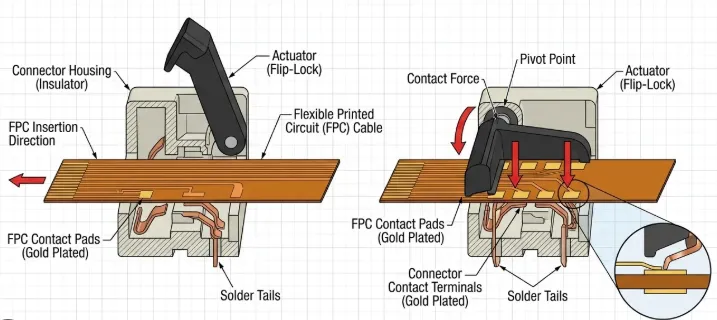
Insertion reliability on a ZIF connector flexible PCB is decided in a few millimeters of the contact zone. Get the gold finger geometry, coverlay setback, or stiffener stack wrong and the connector either refuses to lock cleanly or loses contact after a handful of cycles. Most failures seen in DFM review trace back to the same root: the FPC was laid out without treating the insertion area as a precision mechanical interface.
ZIF connectors rely on a defined slot thickness and a controlled contact wipe. The FPC must enter that slot, present the fingers at the correct height and length, and remain flat under the actuator. Any deviation shows up as high insertion force, incomplete seating, or intermittent opens.
ZIF Contact Zone Geometry That Keeps Fingers Seated
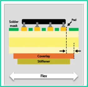
The first requirement is matching the connector's recommended contact length and the position of the coverlay opening. Coverlay must stop short of the finger tips. A typical setback is 0.3–0.5 mm measured from the coverlay edge to the start of the gold surface. Less than that and the coverlay edge can catch on the connector contacts or the locking bar. More than that leaves excess bare copper that collects flux residue or contaminants.
Pitch and finger width have almost no forgiveness on 0.5 mm pitch ZIF parts. Etch tolerance, coverlay registration, and outline routing all stack up. If the finished finger width falls outside the connector's acceptance window, contact force becomes uneven across the row. One or two fingers may never reach the required wipe distance.
Leading-edge geometry matters more than most layouts acknowledge. A sharp 90° outline increases insertion force and can score the connector contacts. A small bevel or radius on the entry edge reduces that risk without changing electrical length.
Gold Finger Length, Width and Thickness Limits
Finger length is not a free variable. Most 0.5 mm and 1.0 mm pitch ZIF connectors specify an exposed length window of roughly 3.0–4.0 mm measured from the coverlay edge to the tip. Shorter fingers bottom out before full contact force develops. Longer fingers hit the rear wall of the housing and prevent the actuator from closing fully.
Width is set by the pad geometry plus etch compensation. Over-etching reduces contact area and, on power fingers, raises current density. Under-etching can cause shorting between adjacent contacts once the FPC is fully inserted.
Copper thickness in the finger zone is usually ½ oz or 1 oz. Thicker copper increases local stiffness. When the stiffener is already near the upper limit of the connector's thickness window, that extra stiffness raises insertion force and can cause the FPC to buckle instead of sliding in. The only thickness that actually matters to the connector is the finished stack height under the contacts—typically 0.30 ± 0.05 mm for common ZIF parts.
How Mating Cycle Requirements Change Plating and Layout
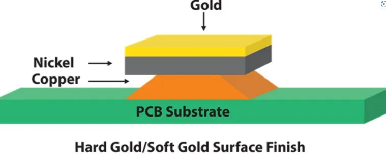
A connector rated for 10–20 cycles can live with a soft gold flash over nickel. Designs that must survive 50 cycles or more need hard gold in the 0.3–0.5 µm range. The nickel underplate thickness and ductility become critical; too thin and the gold wears through, too thick and the finger turns brittle under repeated flex.
Layout must also change with cycle count. High-cycle parts benefit from a slightly wider finger and a more gradual stiffness transition at the stiffener edge. An abrupt change from stiff to flexible creates a hinge line. After repeated insertions the copper cracks or the coverlay delaminates right at that line.
Plating adhesion and surface cleanliness matter more on high-cycle designs. Any residual process chemistry left on the gold surface increases wear rate once the contacts start wiping.
Stiffener Placement and Bond Quality Under the Contact Zone
Without a stiffener the FPC simply buckles. The fingers never present a flat, controlled surface to the connector contacts. Polyimide stiffeners are the usual choice when total thickness must stay low. FR4 is used when higher rigidity or lower cost is acceptable. Thickness is selected so that base copper + adhesive + stiffener equals the connector's specified slot height.
The stiffener must cover the entire contact zone and extend past the coverlay edge into the flexible area—typically 1–2 mm minimum. If it ends exactly at the coverlay opening, every insertion creates a sharp bend right at the copper transition. That is the most common location for cracked traces and delaminated coverlay in the field.
Bond quality is non-negotiable. Voids under the stiffener create soft spots that allow local deformation under the actuator. Adhesive must survive any subsequent reflow or hand-soldering temperature. Pressure and cure conditions during lamination determine whether the bond stays intact after thermal cycling.
Final Layout Checks Against the Connector Drawing
Before release, verify the contact zone against the actual connector datasheet rather than a generic rule set. Confirm exposed finger length falls inside the min/max window. Confirm finished stack thickness under the fingers is inside the connector's acceptance band. Confirm coverlay setback accounts for registration tolerance. Confirm the outline leaves adequate copper-to-edge clearance on the outer fingers. Confirm stiffener material, thickness, and overlap length are called out on the fabrication drawing.
These dimensions are not secondary details. They are the difference between a ZIF interface that seats with consistent force every cycle and one that requires operator pressure or develops intermittent opens after limited use. Treat the insertion area as a precision mechanical interface and the rest of the FPC design stays reliable.