From a fabrication standpoint, the conflict is straightforward: the thicker the copper, the more lateral etch undercut you get, and the wider your minimum 2oz copper FPC trace width and spacing must become. In production we routinely reject or flag fine-pitch flex designs that specify 2oz or 3oz copper because the etch factor collapses below a stable process window. Thin copper (0.5 oz or 1 oz) remains the default for anything under roughly 6–7 mil line/space on FPC. Heavy copper is only viable when the layout can accept 8–12 mil features and the current-carrying requirement cannot be met any other way.
Where Thick Copper Starts to Fight Fine Pitch on Flex
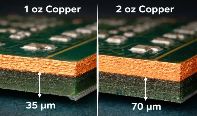
Most FPC manufacturers can hold 3/3 or 4/4 mil on 0.5–1 oz copper with acceptable yield. Once copper moves to 2 oz (≈70 µm) or 3 oz (≈105 µm), the same process window disappears. Side etch becomes comparable to the copper thickness itself, traces develop a pronounced trapezoidal cross-section, and the finished base width can drop below the design value by 40–60 %. At that point opens, neck-downs, and residual copper bridges appear in volume production. The practical decision is therefore binary: either keep the copper thin and widen the power traces, or accept coarser pitch and the accompanying loss of routing density and flexibility.
Side-by-Side Manufacturing Comparison
| Dimension | 0.5–1 oz Copper | 2 oz Copper | 3 oz Copper |
|---|---|---|---|
| Typical min L/S (reliable yield) | 3/3 – 4/4 mil | 8/8 – 10/10 mil | 10/12 – 12/12 mil |
| Etch factor stability | High (EF > 2) | Marginal (EF ≈ 1.2–1.5) | Poor (EF < 1.2) |
| Process risk / yield impact | Low | Moderate–High | High |
| Flexibility / min bend radius | Best | Reduced | Significantly reduced |
| Current capacity (same width) | Baseline | ≈2× | ≈3× |
| Material & process cost | Standard | +20–40 % | +50 % or more |
| Typical FPC applications | Fine-pitch sensors, displays, wearables | Power flex, battery interconnects with relaxed pitch | High-current static flex only |
Quick Decision Matrix for Production Reality
| If your priority is… | Better Choice | Why |
|---|---|---|
| Highest routing density / fine pitch | 0.5–1 oz | Stable etch window and highest yield |
| Maximum current in limited width | 2 oz or 3 oz | Cross-section wins, but only if L/S ≥ 8–10 mil |
| Dynamic flex or tight bend radius | 0.5–1 oz | Thicker copper raises fatigue risk |
| Fast prototype and standard pricing | 0.5–1 oz | Most fabs run these every day |
| Mass production yield stability | 0.5–1 oz (or 2 oz with ≥10 mil rules) | Etch process becomes the limiting factor above 1 oz |
| High reliability under repeated flex | 0.5–1 oz RA copper | Lower residual stress after etch |
How Etching Behavior Changes with 2oz and 3oz Copper
Wet etching is isotropic. The etchant attacks sideways at roughly the same rate it attacks downward. On 1 oz copper the side etch is typically 10–18 µm; on 2 oz it climbs to 30–50 µm and on 3 oz it frequently exceeds 50 µm. When the design calls for a 6 mil (150 µm) trace on 2 oz copper, each side loses nearly the full copper thickness. The remaining base width can fall below 20–30 µm, producing an etch factor near 1.0–1.1. That is the point at which traces open or become mechanically fragile.
In CAM we compensate by oversizing the artwork, but compensation has limits. Once the required oversize approaches the designed spacing, the process becomes unstable. Spray pressure, conveyor speed, and copper-ion concentration must be held tighter than normal production tolerances. Most volume FPC lines are optimized for 0.5–1 oz; pushing them into 2 oz or 3 oz territory for fine features raises scrap rates and forces slower, more expensive process recipes.
Practical Line-Width and Spacing Limits We Enforce
From daily DFM review the numbers are consistent across multiple fabs:
- 0.5 oz / 1 oz: 3/3 mil is routine; 4/4 mil is the comfortable production floor for most FPC shops.
- 2 oz: 8/8 mil is the realistic minimum for stable yield; many prefer 10/10 mil. Anything below 7 mil triggers yield warnings or outright rejection.
- 3 oz flexible PCB: 10/12 mil or larger. Below that the risk of residual copper bridges and open circuits is too high for volume runs.
These are not theoretical limits. They reflect the combination of etch undercut, dry-film adhesion on polyimide, and the dimensional instability of thin flex cores under spray etching. Attempting to force a 4 mil or 5 mil 2oz copper FPC trace width almost always ends with either open circuits after etch or shorts after coverlay lamination.
Additional Process and Material Constraints on Flex
Heavy copper also hurts flexibility. A 3 oz copper layer on a 25 µm polyimide core raises the neutral-axis stress during bending. Minimum bend radius increases and fatigue life drops. Rolled-annealed copper helps, but it cannot fully compensate for the added thickness. Coverlay adhesion becomes more critical because the taller copper features create larger step heights; insufficient adhesive flow leaves voids that later appear as delamination under thermal cycling.
Panel utilization suffers as well. The longer etch times required for 2 oz and 3 oz copper reduce line throughput. Some fabs must run these panels on dedicated slower lines or with reduced spray pressure, both of which raise cost and extend lead time.
What the Factory Sees During CAM and Yield Review
When a fine-pitch FPC arrives with 2 oz or 3 oz copper, the first CAM checks are etch-factor calculation and minimum remaining base width after expected undercut. If the predicted base width falls below roughly 40–50 % of the design width, we either request a copper-weight reduction or an increase in line/space. Panel utilization is recalculated because heavier copper often forces lower panel density or special handling to avoid wrinkling on thin polyimide.
Inspection criteria tighten. AOI and electrical test thresholds are adjusted for the higher likelihood of neck-downs. In volume we see yield drops of 5–15 % when designers ignore the copper-thickness versus feature-size relationship. The recommendation that leaves the DFM meeting is almost always the same: keep signal layers at 0.5–1 oz and move high-current nets to wider traces or dedicated power layers if the stack-up allows.
Which Option Should You Choose?
Choose 0.5 oz or 1 oz copper if you:
- Need line/space below 6–7 mil for density or impedance control
- Require dynamic flex or a tight bend radius
- Want the highest production yield and shortest lead time
- Are working within standard FPC pricing and process capability
Choose 2 oz copper if you:
- Can open the design rules to ≥8–10 mil line/space
- Need roughly double the current capacity without adding layers
- Accept a moderate increase in cost and a reduction in flexibility
- Have confirmed the fab’s specific etch capability for 2 oz on flex
Choose 3 oz copper only if you:
- Can live with ≥10–12 mil features and primarily static flex applications
- Have no other way to meet current or thermal requirements
- Are prepared for higher cost, longer process times, and tighter process control
In most fine-pitch FPC work the better manufacturing choice remains thin copper plus appropriate trace widening or additional layers. Heavy copper is a tool for power delivery, not for density.
Recommended Figure: Decision flowchart starting from required current and minimum pitch, branching to recommended copper weight and corresponding design-rule adjustments.
Frequently Asked Questions
Q1: Can a fab actually produce 5 mil / 5 mil traces on 2 oz copper FPC?
A1: In theory some advanced lines claim it; in practice yield collapses. Side etch removes too much copper and residual bridges become common. Most volume manufacturers will advise against it or quote it as a high-risk, high-cost special process.
Q2: Why does 3 oz flexible PCB cost so much more than 1 oz?
A2: Longer etch times, lower panel throughput, higher material cost, increased scrap risk, and often the need for dedicated process parameters all add up. Flexibility and coverlay adhesion issues further raise the inspection burden.
Q3: Is there a way to keep fine pitch and still get higher current capacity?
A3: Yes—use thin copper on the signal layers and either widen the power traces, add parallel traces, or move high-current nets to a separate thicker layer if the stack-up permits. Selective plating or dual-copper constructions are also options, but they add process steps.
Q4: How much does heavy copper reduce FPC flexibility?
A4: Noticeably. Minimum recommended bend radius increases and cycle life under dynamic flex drops. For applications that must bend repeatedly, 2 oz is already a compromise; 3 oz is usually limited to static or very large-radius bends.
Q5: What is the safest 2oz copper FPC trace width for production?
A5: 8–10 mil line and space. Below 8 mil the etch factor becomes marginal and yield variability rises. Always confirm the specific fab’s capability before locking the design.
Q6: Should I specify starting copper or finished copper when ordering 2 oz / 3 oz FPC?
A6: Clarify both. On outer layers plating adds copper; on inner layers the foil weight is essentially the finished weight. Ambiguous call-outs lead to the wrong starting foil and unexpected undercut.