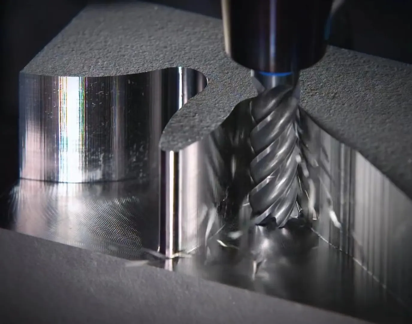
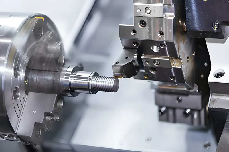
We run parts down to 0.8 mm walls in aluminum on a regular basis when the geometry supports it and the height stays reasonable. CAM programmers set conservative stock allowances and program light finishing passes with reduced stepover to keep the wall from pushing away. For steel we usually stay at 1.0–1.5 mm minimum and plastics start around 1.5 mm because they move too easily under the tool. These numbers come straight from what actually clears inspection without constant rework on the floor.
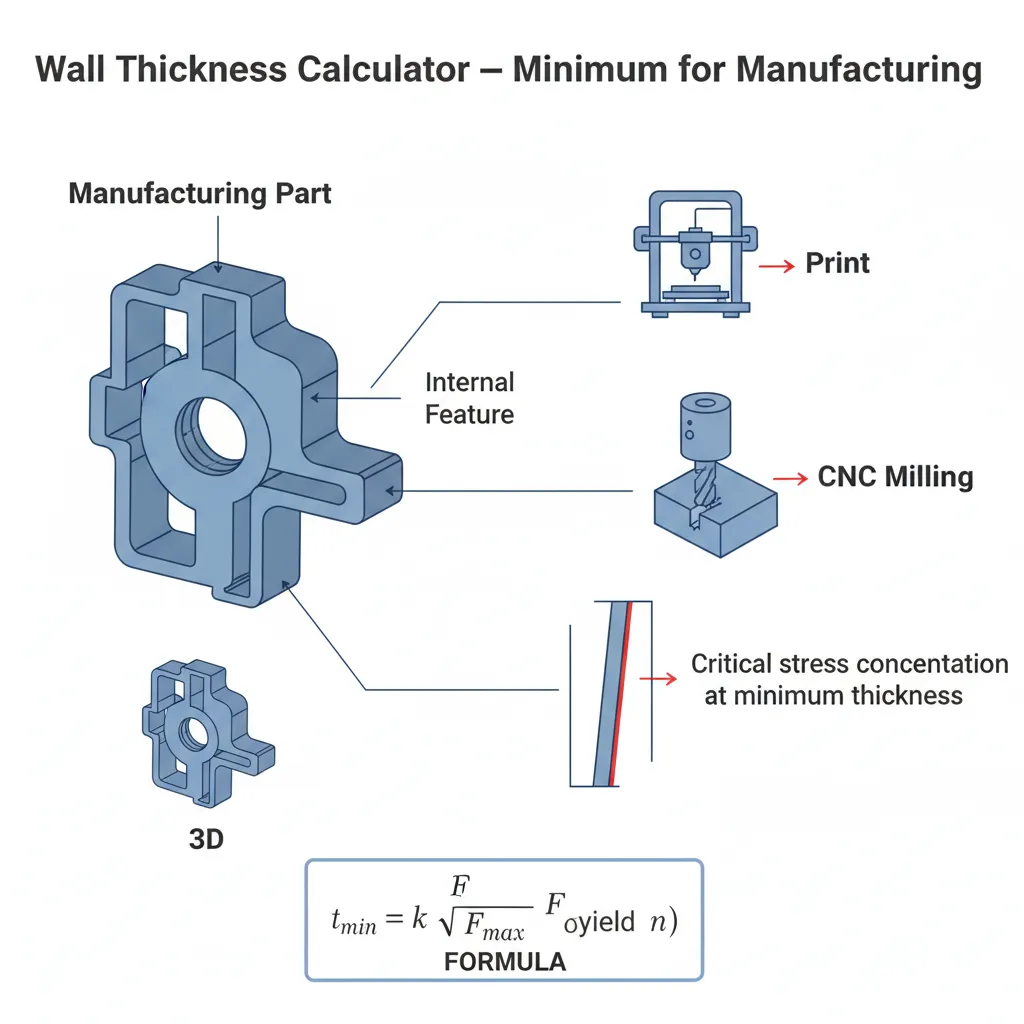
How material stiffness drives the limits we see on the machines
Aluminum 6061 or 7075 gives us the most flexibility because it cuts cleanly and dissipates heat well, so 0.8 mm walls hold up during finishing if the unsupported height stays under about 8 times the thickness. Steel and stainless need more meat because the higher cutting forces cause chatter and the material work-hardens, pushing our safe zone to 1.0 mm and often 1.5 mm for taller features. Plastics like ABS, Delrin or nylon act soft and hold heat, so anything under 1.5 mm starts deflecting or melting at the tool edge. What we typically see on the CAM side is designers sending files with uniform 0.5 mm walls across all materials without accounting for these differences, which forces us to flag the job early.
Where thin wall deformation shows up first during roughing
The issue appears when the height-to-thickness ratio exceeds 5:1 to 8:1 depending on material. On tall thin aluminum walls the tool pressure deflects the feature outward during side milling, leaving tapered dimensions or chatter marks. In steel the vibration amplifies quickly and can even shift the part in the vise. Plastics warp from localized heating because they don't conduct heat away, so the wall bows after a few passes. This shows up consistently on parts where the designer chased minimum weight without adding any supporting geometry.
What actually happens on the floor when walls drop below recommended CNC machining wall thickness guidelines
Parts come off the machine with walls measuring under nominal on one side and sometimes wavy surface finish. We see scrap rates jump because tolerances can't be held, especially on features that need to mate during assembly. In aluminum a 0.5 mm wall might pass visual but fail caliper checks after stress relief or anodizing because residual deflection relaxes. Steel parts show tool marks or even cracks at the base. Plastics often require rework for melted edges or permanent bow. This delays shipment and increases cost when we have to run slower programs or add extra fixturing steps.
How we adjust programs and fixturing to keep thin walls stable
CAM engineers leave extra stock on thin features during roughing—typically 0.5–1 mm—then take multiple light finishing passes with stepover under 10% of tool diameter. We use climb milling where possible to push the wall into the fixture rather than pull it away. For critical jobs we add temporary support ribs or tabs in the model that we machine away at the end. Fixturing uses soft jaws, vacuum plates or low-melt alloys to support the entire back side. Cutting parameters drop feed and depth of cut to limit force while maintaining sharp tools with high helix angles. These steps keep deflection under control and let us hit tolerances without heroic efforts.
Reinforcement ribs and design adjustments that make the biggest difference
When weight is critical we recommend ribs at 50–60% of the main wall thickness placed every 20–30 mm. Rib height stays under 3 times its own thickness so they don't become thin walls themselves. Gussets at corners and fillets at base transitions add stiffness without much added mass. We also ask designers to keep wall height under 5–8 times thickness for unsupported sections. These changes let us run standard parameters instead of babying every pass. On the shop floor this translates to higher first-pass yield and fewer DFM back-and-forths.
Material-specific thickness ranges we quote against in production
For aluminum alloys we treat 0.8 mm as the reliable minimum for production with short walls and 1.0–1.5 mm preferred for anything taller. Stainless and carbon steels start at 1.0 mm safe, 1.5 mm common. Titanium needs 1.5–2.0 mm because heat buildup is unforgiving. Plastics require 1.5 mm minimum and often 2.0 mm for stable dimensions after cooling. These are the numbers that let us maintain consistent cycle times and meet print without constant operator intervention.
When we can relax the standard minimums on a job
Exceptions happen on prototype parts with short walls under 10 mm tall, relaxed tolerances, or when the customer accepts higher scrap risk and we add custom fixturing. Aerospace weight-saving designs sometimes push aluminum to 0.5 mm with extensive support features and slower programs. In those cases we document the trade-offs on the DFM report and machine in multiple setups. For most commercial work though, staying at the standard guidelines keeps delivery on time and cost predictable.
Running thin walls successfully comes down to matching geometry to material behavior and using proven shop techniques rather than pushing absolute minimums. When files come in respecting these CNC machining wall thickness guidelines we clear them through CAM review quickly and deliver parts that perform in the field. Talk to us early on aggressive designs so we can suggest the adjustments that keep both quality and schedule intact.