There's something special about watching a maker's idea jump from breadboard chaos to a clean, professional device that actually lives on a desk or wall. That's exactly what happened with this IoT-based particulate matter and air quality monitoring system. The creator set out to build a practical tool that measures PM1.0, PM2.5, PM10, temperature, humidity, IAQ, VOC equivalent, and CO2 equivalent, then displays everything both on a tiny 0.96-inch OLED and on a polished web dashboard hosted by the ESP32 itself.

The goal was clear: create something useful for tracking indoor air quality, dust, smoke, or outdoor pollution without relying on commercial black-box gadgets. Live readings, historical graphs, data logging with Excel export, and configurable alerts all had to work smoothly. Breadboards and jumper-wire nests can prove the concept, but they never deliver the reliability, compact size, or clean power that sensors like the PMS7003 and BME680 demand. That's where a properly designed custom PCB becomes the real hero of the story.
What You Actually See When the System Comes Alive
The finished device is more than a sensor box. On the local OLED you see real-time values updating cleanly. Open a browser to the ESP32's IP address and a modern web dashboard appears: an IAQ circular gauge that changes color with air quality level, live cards for every PM fraction and environmental parameter, a PM trend graph spanning 15 minutes to 24 hours, a history and data-logger page that can start and stop recording, Excel export, and an alerts page with user-settable thresholds.
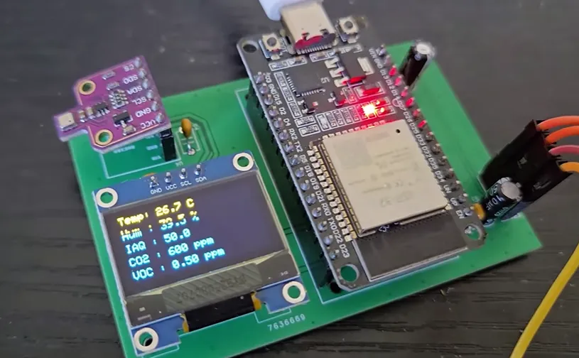
The hardware choices support that experience. The Plantower PMS7003 pulls air through its laser chamber and reports particle concentrations over UART at 9600 baud. The BME680, running the BSEC library, delivers temperature, humidity, and the calculated IAQ/VOC/CO2 numbers over I2C. Both sensors share the ESP32, which also drives the OLED on the same I2C bus and serves the entire web interface.
Figure: ESP32 Air Monitor hardware
What elevates the project is the move from prototype wiring to a purpose-built board. All critical modules sit on the front side. Female headers let the ESP32, OLED, and BME680 be swapped or upgraded later.
Figure: Assembled air monitor set
The PMS7003 connects with short jumper wires so its intake can sit in free air—critical for accurate laser scattering. Decoupling capacitors (10 µF electrolytic and 0.1 µF ceramic) sit right next to the power pins, quieting the rails that feed the sensitive gas and particle sensors.

The result feels finished. No rat's-nest of wires, no intermittent readings from loose connections, and a dashboard that looks like something you would actually leave running on a home network.
The PCB Board That Made the Sensors Behave
The board is a straightforward yet carefully considered 2-layer design optimized for hand assembly and sensor performance:
|
Parameter |
Value / Choice |
Why It Matters |
|---|---|---|
|
Layers |
2 (double-sided) |
Cost-effective, sufficient for this mixed-signal IoT board |
|
Material |
Standard FR-4 |
Good mechanical strength and everyday thermal stability |
|
Thickness |
Typically 1.6 mm |
Rigid enough for headers and handling |
|
Copper |
1 oz |
Adequate for ESP32 currents and short sensor runs |
|
Surface finish |
Clean plating (HASL or ENIG style) |
Reliable through-hole soldering |
|
Component style |
Mostly through-hole + female headers |
Easy hand assembly and future module swaps |
|
Sensor placement |
Front side, PMS7003 off-board via jumpers |
Clear airflow and thermal isolation |
|
Power decoupling |
Local 10 µF + 0.1 µF near sensors |
Reduces noise on BME680 gas readings and PMS7003 UART |
Layout priorities were simple: keep I2C lines short and clean between ESP32, BME680 and OLED; give the PMS7003 physical freedom for airflow; and place capacitors close enough to actually do their job.
The Real Friction Points That Showed Up Along the Way
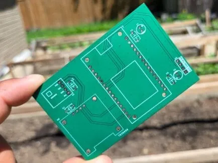
Even a "simple" 2-layer sensor board has real traps. The BME680's gas sensor is sensitive to both electrical noise and local heat. The PMS7003 needs unobstructed airflow and a stable 5 V rail. The ESP32's Wi-Fi activity can inject noise if the power distribution is careless. On a breadboard these problems hide behind intermittent readings; on a finished product they become permanent flaws.
Power integrity was the first practical hurdle. Without local decoupling the 3.3 V and 5 V rails can dip or ring when the ESP32 transmits or the PMS7003 fan spins up. That noise shows up as wandering IAQ numbers or occasional UART glitches. Placing the capacitors right at the supply pins of each module solved it.
Physical placement mattered just as much. Putting the BME680 too close to the ESP32 or a regulator would heat the sensor and skew temperature and gas readings. The PMS7003 cannot be boxed in; its laser chamber needs a steady air stream. Using headers and short jumpers gave the mechanical freedom the sensors required.
On the manufacturing side, 2-layer boards still need careful Gerber hygiene. Outline layers must match, silkscreen must clear pads and vias, and annular rings around through-holes must be adequate. I've watched almost identical issues surface during CAM review on the 2-layer FR4 job—mismatched board outlines that would have caused routing misalignment, tight-pitch holes that broke annular rings, and silkscreen that overlapped mask openings.
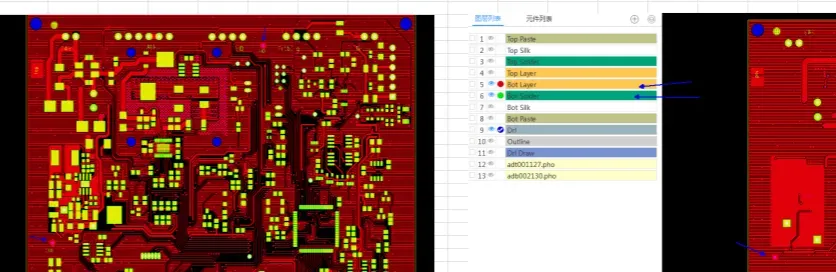
In one recent case the CAM team caught exactly those problems, confirmed dimensions with the designer, adjusted clearances, and filled problematic grid areas so the boards came out clean on the first run. Early clarification like that prevents the majority of downstream scrap and delay. The same discipline applied here kept the air-quality boards free of those classic 2-layer gotchas.
How AIVON PCB Made This Project Possible
Once the schematic lived in EasyEDA and the layout looked solid, the Gerbers went straight to manufacturing. The boards arrived in three days—clean, professional, with crisp silkscreen and reliable through-hole plating. That short turnaround is more than convenience; it keeps the creative momentum alive. A maker can design on a weekend, order, and be soldering the next week instead of waiting weeks for a revision cycle.
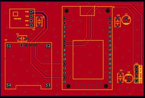
The physical board itself elevated the project. Because everything sits on a rigid, properly routed substrate, the I2C bus stays quiet, the power rails stay stiff, and the mechanical connections stop working loose. Female headers turned the ESP32, OLED and BME680 into swappable modules. The off-board PMS7003 placement guaranteed the airflow the laser sensor needs. The result is a device that looks and behaves like a finished product rather than a temporary experiment.
Manufacturing precision matters for sensor work. Consistent copper, good plating, and accurate hole registration mean the UART and I2C signals arrive clean. Local decoupling footprints placed correctly do their job. The same CAM attention that catches outline mismatches and silkscreen conflicts on other 2-layer FR4 projects ensured these boards needed no rework before assembly. That reliability lets the creator focus on firmware polish—the dashboard graphs, the Excel export, the color-changing IAQ gauge—instead of chasing intermittent hardware bugs.
In short, the custom PCB didn't just hold the parts together. It removed the electrical and mechanical noise that would have undermined the sensors, gave the project a professional appearance, and shortened the path from idea to a device you can actually leave running and trust.
Quick DFM Checklist for Similar ESP32 Sensor Boards
|
Checkpoint |
What to Verify |
Why It Matters Here |
|---|---|---|
|
Local decoupling |
10 µF + 0.1 µF within a few mm of every power pin |
Protects BME680 gas readings and UART stability |
|
Sensor thermal & airflow isolation |
BME680 clear of heat sources; PMS7003 free to breathe |
Prevents temperature drift and particle errors |
|
I2C routing |
Short runs, away from switching noise |
Keeps OLED and BME680 communication clean |
|
Through-hole annular rings |
Adequate copper around every plated hole |
Survives hand soldering and mechanical stress |
|
Silkscreen clearance |
No overlap on pads or vias |
Readable board that survives assembly |
|
Outline & mechanical data |
Matching GKO / outline layers |
Avoids CAM hold-ups and depanelization defects |
|
Header & jumper strategy |
Female headers + flexible sensor leads |
Serviceability and correct sensor placement |
From One Working Unit to Something You Can Rely On
This project is a textbook example of what happens when a clear idea meets solid board-level thinking. The creator started with useful sensors and a desire for live data, history and alerts. By moving to a compact 2-layer PCB with thoughtful placement, proper decoupling and modular connections, the device became reliable enough to monitor real air every day. The quick turnaround and clean manufacturing simply let that vision arrive sooner and work better.
If you have an IoT sensor idea still living on a breadboard, the same path is open: lock the electrical design, respect the sensors' physical needs, run a quick DFM pass, and get a proper board made. The gap between a temporary prototype and a tool you trust is often just one well-executed PCB away.
FAQ
Q1: Is a 2-layer board really enough for an ESP32 air-quality monitor?
A1: Yes. With solid ground pour, short sensor runs and local decoupling, a 2-layer layout handles the UART, I2C and moderate currents without trouble. Four layers help denser RF designs, but they are not required here.
Q2: How close do the decoupling capacitors need to be?
A2: Within a few millimeters of each sensor's power pins. The BME680's gas measurements and the PMS7003's laser readings are both sensitive to supply noise; distant capacitors simply do not filter the frequencies that matter.
Q3: Should the PMS7003 be soldered directly to the board?
A3: Usually not. Short jumpers or a header keep its intake in free air. Mounting it flat against the PCB often reduces particle measurement accuracy.
Q4: What CAM issues show up most often on these 2-layer sensor boards?
A4: Mismatched outline layers, silkscreen overlapping pads, insufficient annular rings, and missing solder-mask openings. Catching them early prevents production delays and both cosmetic and electrical defects.
Q5: Are female headers worth the extra height?
A5: For prototypes and early units, yes. They let you swap an ESP32, OLED or BME680 without desoldering—valuable while firmware is still changing or if a module fails.
Q6: What board thickness and finish work best for hand assembly?
A6: 1.6 mm FR-4 gives good rigidity for headers. A clean HASL or ENIG finish makes through-hole soldering reliable without special techniques or extra flux.