When a panel package lands on our CAM desk at AIVON, depaneling is often already written as V-cut — V-score or V-groove scoring, if that is the wording on the drawing. The forming-method note says V-cut. The panel title block may say it again. What we still have to find is the score itself: which array seams, which outer edges, whether the process edge is included, how remaining thickness and angle are controlled, and what copper or stamp holes already sit on that web. Those are the holds this article covers. The word "V-cut" in a note is not a toolpath, and it is not permission to leave copper open on the finished edge.
| What the order appears to say | What we actually receive | What we ask the customer to confirm |
|---|---|---|
| Panel requires V-cut | Forming-method note or panel title block names V-cut; no score path on the drawing | Which array seams and outer edges are scored, and whether the process edge is included |
| Remaining thickness and angle are specified | Order values of 0.013 in (0.33 mm) remaining thickness after V-cut and 60°, with no remaining-thickness tolerance | Whether 60° is accepted or replaced, and how remaining thickness is controlled |
| Connecting tabs are designed for depaneling | V-cut and a stamp-hole row (mouse bites) sit on the same connecting tab | Keep one singulation method on that web, or accept the weaker tab in transit |
| Lands sit inside the finished outline | SMT lands sit close to a candidate scored edge | Pull or move copper, change forming on that edge, or accept exposed copper after V-cut |
PCB V-Cut Location When the Panel Drawing Only Names the Process
We start with ownership of the method, before angle or copper. On one order the panel drawing required V-cut and gave no V-cut location. The note had already named the process. The sketch had not placed a line for the PCB panelization.
A forming-method note is not a score path. We still need which array seams are cut, which outer edges, whether the process edge is scored, and where each line starts and ends. The board outline — GKO or the mechanical layer in the file list — shows the finished contour of one unit. It does not place a V-cut. Array ticks, dimension arrows, or a drawn score on the panel sketch are what we use. When those marks are missing, there is nothing to program.
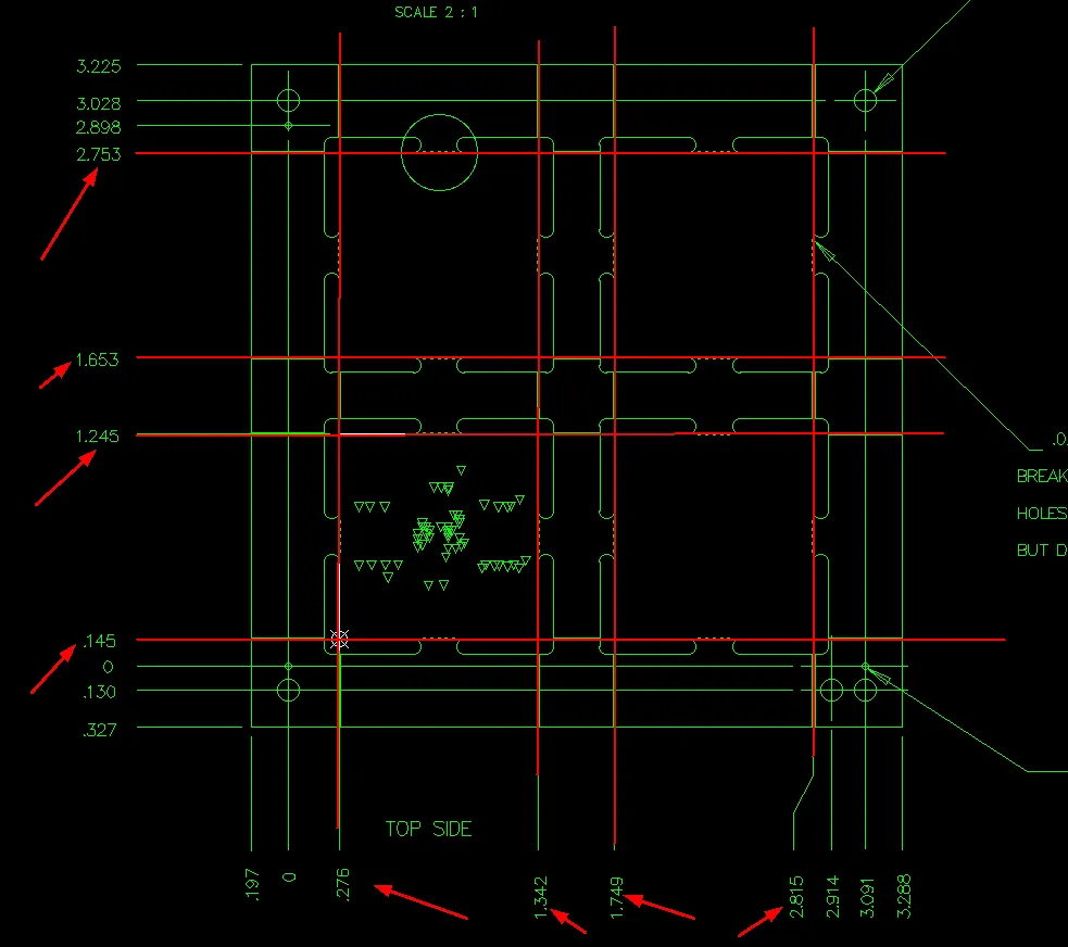
The panel drawing customer provided includes V-cut requirements, but does not specify the exact V-cut positions. We suggest making V-cut along the red lines shown in the attached drawing.
V-cut is a straight score. We do not read a jog, a partial seam, or "score only the long edges" out of a one-line process note, and we do not invent a line on a rectangular outline because the units look regular. Three objects in the same package have to agree: the order or forming-method note, the panel drawing, and outer copper. Method without location is the first hold we send.
We read the note and the panel drawing together and mark every seam and outer edge that could take a score. If only the word "V-cut" exists, we ask the customer to place the lines or to accept a factory panel sketch that shows them. We do not pick the seams from the outline alone.
What Panel Drawing and Copper Overlay Show for V-Scoring
Once a candidate path exists — drawn, dimensioned, or proposed on a sketch — we use one comparison set for the rest of the review: panel drawing, board outline, outer copper, stamp-hole drill tools only, and the forming note. Overlay tells us what is already in the files. It does not choose the forming method for the customer.
| Overlay can show | Overlay cannot show |
|---|---|
| Whether a drawn or dimensioned score coincides with an array seam or with the finished outline | Which unused rectangular edge was meant when no path is drawn |
| Whether a stamp-hole row already sits on that same seam | Whether V-cut plus stamp holes on one connecting tab still leave enough web for handling and transit |
| Whether outer copper, SMT lands, or plane pour cross the candidate score or sit on the finished edge after the groove is cut | That copper still inside the Gerber outline will stay closed after scoring — the groove removes laminate and can open copper that looks inside the contour |
| Whether the note states remaining thickness, angle, or both, and whether a tolerance sits next to those values | That a stated angle is a blade we can mount, or that a remaining-thickness value with no tolerance is a controllable process limit |
| Units as released (inch and millimetre if both appear) | A default remaining thickness, a default angle, or a numeric pad-to-score keep-out that is not in this package |
Proximity on a 2D screen is not the same as the finished edge after the groove. Two singulation features on one tab are not the same as an acceptable remaining web. Those questions stay on the order; overlay only shows that they are in the files.
PCB V-Cut Angle and Remaining Thickness Written Without a Tolerance
Location can be settled and the process values still stop the job. Remaining thickness after V-cut is the laminate left between the top and bottom grooves. Angle is the included angle of the groove. Neither arrives with the word "V-cut." Both belong on the forming note or the panel drawing.
One package we reviewed listed forming as V-cut and gave remaining thickness 0.013 in and a V-cut angle of 60°, creating clear PCB V-Cut manufacturing limitations during DFM review. Those stay quoted order values. We do not treat them as industry defaults, and we do not add a blade catalog or a remaining-thickness table from outside the package.
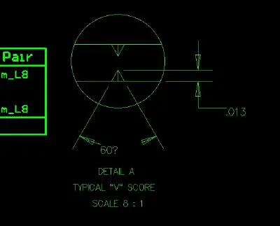
gave remaining thickness 0.013 in and a V-cut angle of 60°
Two problems sat in that same note, and we keep them separate. Angle is a process input. On that job we did not run a 60° blade, so the note could not be built as written. We do not swap in another angle in CAM and ship it. Remaining thickness with no tolerance is a target without a control window. A single number is not both nominal and limit, which is why that EQ also said remaining thickness would be hard to control as released.
Changing angle changes how much edge laminate the groove consumes. That is why the same values show up later when lands sit on the scored edge. We record the coupling; we do not turn this section into a pad-clearance rule.
We pull every remaining-thickness and angle callout from the note and the panel drawing, with the units as released. If no plus/minus or process window sits next to remaining thickness, we ask for one — or for permission to use our controlled remaining-thickness process without treating the single released number as a limit. Angle is accepted as written, replaced by a customer-approved angle, or the forming method is changed. We do not pick the angle ourselves.
V-Cut and Stamp Holes on the Same Connecting Tab
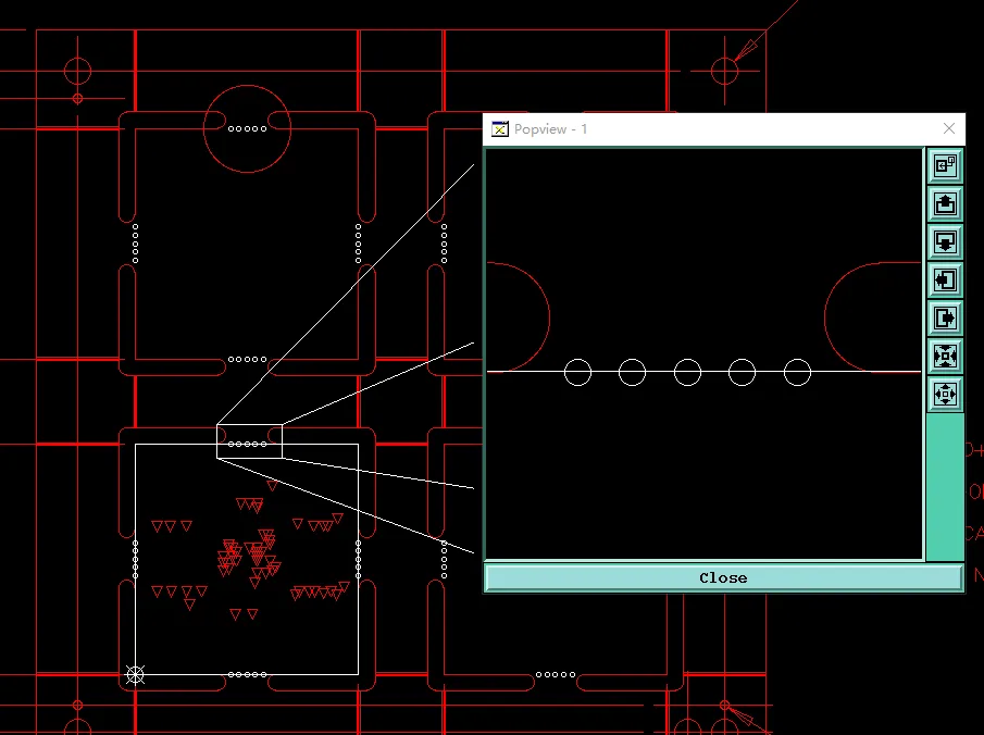
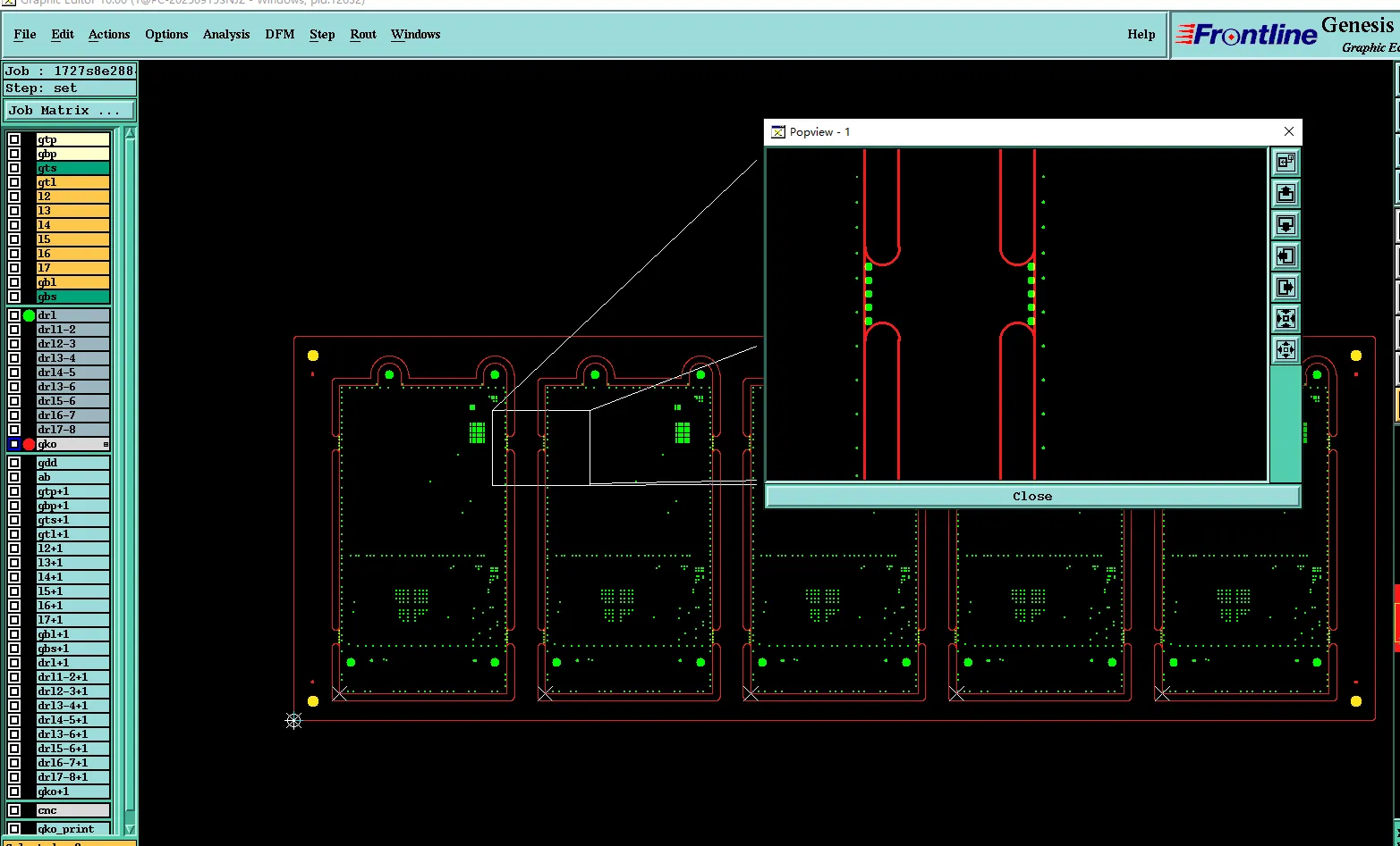
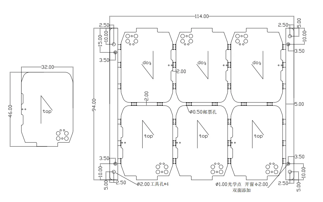
Another order had V-cut on the panel drawing and a stamp-hole row on the connecting tab. V-cut thins the web along a continuous score. The stamp-hole row perforates that same remaining web. Together they remove more connecting laminate than either method alone. We do not treat stamp holes as wrong and we do not treat V-cut as wrong. Both features were drawn on the tab the panel still needs for handling and transit.
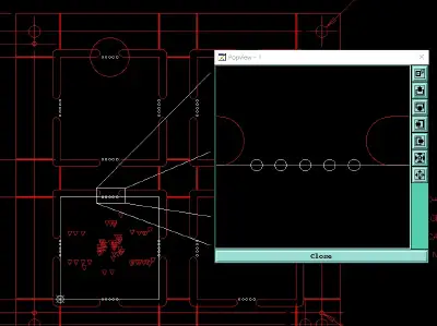
The panel drawing you provided includes V-cut requirements, but the connecting bridges are also designed with stamp holes.
Board-to-board gap, hole-to-hole spacing, and remaining thickness after V-cut are different measurements. We do not fold them into one "bridge" width unless that is the customer's wording. Overlay already showed both features present. It did not tell us the web would survive shipping. The EQ on that job named the risk: connecting strength drops, and the panel can break in transit. We do not invent a strength number for the tab.
If V-cut is the intended singulation, stamp holes on that seam are extra perforation. If stamp holes are the intended singulation, the V-cut callout is the extra cut. We list seams as V-cut only, stamp-hole only, or both, then ask which method that tab is supposed to keep: keep V-cut and remove the stamp-hole row; keep the stamp-hole row and drop V-cut on that seam; or accept both and the weaker web. Moving holes along the outline is a different review. It is not the close on this hold.
Pads Close to the V-Cut Edge and Exposed Copper After Scoring
A V-cut is a groove with width and remaining thickness, not the zero-width outline line in Gerber. Pads can look clear of the contour on a 2D overlay and still open on the finished edge after the groove is cut. That is the finding we send when lands sit too close to a scored edge, creating a V-CUT edge clearance concern.
On one job the arrowed SMT lands sat so close to the board edge that V-cut would leave exposed copper. Lands, plane pour, and traces are different objects; this hold was the lands at the arrow. Angle and remaining thickness, already taken from the note, change how much edge material the groove takes. We point back to those released values. We do not invent a keep-out and write it as a factory rule.
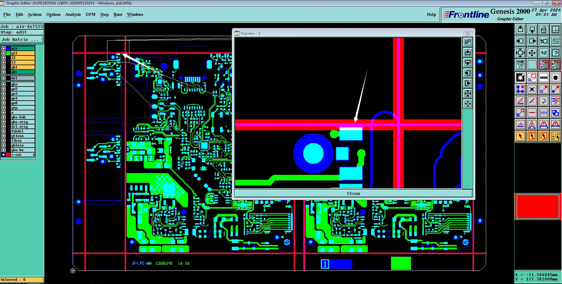
The pad close to the board edge that V-cut would leave exposed copper
The board that leaves the scorer is not the pad shape in the Gerber if the groove clips the land. Exposed copper after scoring is a finished-edge condition, not only a color on a DRC screen. We overlay outer copper and SMT lands on the candidate path and on the finished outline at those sites, and we mark which lands the groove as drawn would open or clip.
What we cannot do on our own is shave the pad in CAM, pull the score off the outline, or switch that edge to route or stamp holes. Those are the choices we send: move or reduce the land / pull copper back from that edge; move or drop V-cut on that seam; or accept exposed copper at those sites.
What We Confirm Before Releasing PCB V-Cut
Each hold maps to a decision we can put on the panel drawing or in the order note, so scoring, stamp-hole drill, and outline route do not disagree at the machine.
| Finding on the order | Close we can release |
|---|---|
| Panel drawing requires V-cut but does not place the score | Customer adds V-cut lines on the panel drawing, or accepts a factory panel sketch that shows seams and whether the process edge is scored |
| 60° and 0.013 in / 0.33 mm remaining thickness, no remaining-thickness tolerance | Customer keeps both values with the process exception on our side; changes angle and/or remaining thickness; or adds a tolerance / accepts our controlled remaining-thickness process. No silent angle swap |
| V-cut plus stamp holes on one connecting tab | Keep V-cut and remove stamp holes on that tab; keep stamp holes and remove V-cut on that seam; or accept both and the transit-break risk named in the query |
| Lands at the arrow on a scored edge | Pull or move copper; change forming method on that edge; or accept exposed copper after V-cut |
Before the traveler goes out, we read the package once more as a set. Forming note and panel drawing name the same method. Every intended seam has a drawn or dimensioned V-cut path. Remaining thickness and angle, if stated, include a way to control them — a tolerance, or an explicit accept of our process. No stamp-hole row sits on a tab that is also scored unless that mix is accepted. No land or pour sits on the scored edge unless exposed copper after V-cut is accepted.
FAQ
Q1: What is V-cut on a PCB?
A1: V-cut is a straight groove scored into the panel so units can be snapped apart at a defined seam. In our review the objects that matter are the forming-method note, the score path on the panel drawing, remaining thickness after V-cut, V-cut angle, and whether copper or a stamp-hole row already occupies that same web.
Q2: What is remaining thickness after V-Cut, and how is it different from V-Cut depth?
A2: Remaining thickness is the laminate left between the top and bottom grooves. Depth language in a note is easy to read as a cut from one side only. We record the value the package actually printed. On the job above that value was 0.013 in (0.33 mm). A number with no tolerance is still only a target until a control window or an accepted process is confirmed.
Q3: What is the tolerance for V-scoring on PCBs?
A3: There is no remaining-thickness or angle tolerance we treat as a default on every order. Tolerance, when it exists, has to sit next to the value on the forming note or the panel drawing. On the package above, remaining thickness was given as 0.013 in (0.33 mm) with no plus/minus and no process window, which is why we could not control that number as written. The close on that job was to add a tolerance, or to accept our controlled remaining-thickness process without reading the single released number as a limit. We do not write a factory tolerance table into CAM and apply it silently.
Q4: What are the differences between break routing and V-cut for PCB design?
A4: V-cut is a straight score that leaves remaining thickness in the web so the panel can be snapped. Break routing follows the board outline — or the outline of a connecting tab — with a router. The routed edge is a milled contour, not a groove. V-cut cannot follow a jog or an irregular outline; routing can. V-cut and outline route are different forming methods, and neither is the same as a stamp-hole row. When lands sit too close to a scored edge, one close we send is to drop V-cut on that seam and form it by route or stamp holes instead. That change has to be confirmed. We do not convert a V-cut callout into break routing in CAM because the outline looks routable.
Q5: What V-Cut angle should be specified?
A5: Angle is the included angle of the groove and is a process input. That package specified 60°. Whether the angle can be run as written is a confirmation on the order, not a published blade list. Changing angle changes how much edge laminate the groove consumes and can change whether lands at that edge stay closed.
Q6: Can V-Cut and stamp holes be used on the same connecting tab?
A6: They can be drawn that way. Overlay will show both. V-cut thins the tab; the stamp-hole row perforates what is left. The question we send is which method that web is supposed to keep, or whether the weaker tab and the transit-break risk are accepted.