A 4 mil backdrill stub, a countersink depth of 0.85 mm ±0.2 mm on a 0.8 mm finished board, or a tight press-fit window on holes 2.0 mm and above can become a CAM question when the hole requirement does not line up with the released stackup, finished thickness, or drilling capability. The note and hole chart may define the process and the target value, but CAM still has to check whether the released construction and geometry support that requirement.
Recent packages raised the same type of conflict in three different ways. A 4 mil remaining stub sat beside a stackup that still had to account for bit point angle, dielectric thickness above the last connected layer, and registration to the primary hole. A countersink calculated at 0.85 mm ±0.2 mm appeared in the same package as a 0.8 mm finished-thickness requirement. Press-fit was applied to tools 2.0 mm and above with a finished-size window that the factory said would be difficult to hold with the stated alignment and drill-bit variation. In each case, the CAM question was whether the released depth or finished-size requirement could remain unchanged after those conditions were compared.
The three EQs below are examples from those jobs. A missing start side, stop layer, or countersink sketch would create a different review. The files being compared remain the same.
| What we saw in the files | Where the files disagreed | What the EQ asked |
|---|---|---|
| Backdrill remaining stub specified as 4 mil against the stackup already in the ZIP | Limited margin for dielectric variation, bit point angle, and registration to the primary hole | Whether 4 mil remains the required remaining stub, whether a different stub is acceptable, or whether those vias run without backdrill |
| Countersink required; calculated depth 0.85 mm ±0.2 mm; finished board thickness specified as 0.8 mm | The cone occupies Z; a depth band that starts near or past finished thickness leaves limited laminate under the point of the bit | Whether thickness changes, whether sink depth or major diameter is reduced, whether L1/L2 copper may be removed, or whether the countersink is omitted |
| Press-fit marked on the chart or note; hole-size tolerance attached to tools 2.0 mm and above | The same finished-hole window is more difficult to demonstrate on a large diameter once alignment and drill-bit error are included | Whether press-fit remains at the released window, whether the customer restates the window, or whether those tools run as standard plated holes |
PCB Backdrilling, Countersink, and Press-Fit Holes in the Released Package
The fabrication note, the hole chart, the NC tools, the stackup or finished-thickness call, and the copper files often describe the same hole in different terms. One source may specify a remaining stub. Another may show a countersink. A third may mark press-fit and a finished-size window. Start side, stop layer, sink side, countersink angle, major diameter, and plating class are frequently spread across those sources rather than collected on a single line.
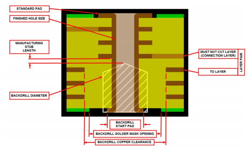
Backdrilling is a second controlled-depth pass on a plated via. Unused barrel is removed so that a short remaining stub is left from the last connected layer. The electrical value is that remaining length, not the programmed machine depth by itself. A countersink is a conical form for a fastener head. Its depth has to fit within finished thickness and has to be reconciled with any copper on L1 or L2 at that location. A press-fit hole is a plated barrel whose finished diameter after plating is the pin interface. The chart value is that finished window, which is a different object from a generic PTH drill tolerance.
A plated flag on the chart does not automatically make a hole press-fit. A depth note does not automatically make a hole a backdrill. A large tool does not automatically make a hole a countersink. Gold-finger bevel and flat-bottom counterbore are adjacent features; they are outside the three findings discussed here.
It is useful, before the overlay, to record which claim comes from the note, which from the chart or sketch, and which is inferred only from pad geometry, so the three processes are not collapsed into a single "special hole" row.
Stub Length, Countersink Depth, and Press-Fit Hole Tolerance on the Drill Drawing
Overlay of drill against copper and the stackup drawing shows tool diameter versus pad, the plated or non-plated flag on the chart, a second tool at the same XY as a primary via when one exists, and whether a stub, sink, or press-fit note is attached to that tool. Finished thickness appears on the drawing or stackup. Copper on L1, L2, and the last connected inner layer appears in the Gerber.
The same overlay does not establish the residual stub after press and dielectric variation, the countersink depth after bit angle and surface reference are set, or the finished PCB hole after plating, wander, and bit wear. It also does not establish whether the designer intended remaining stub, Z-depth from the surface, or protection of a named layer.
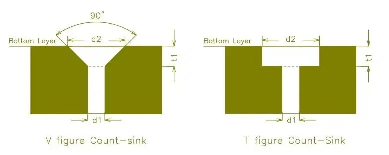
Board thickness is an input to both backdrill depth and countersink depth. A finished thickness of 0.8 mm and a calculated sink of 0.85 mm ±0.2 mm in the same package therefore belong to one comparison. A 4 mil stub is a remaining-barrel value. Start side, last connected layer, and the dielectric above that layer still have to be taken from the stackup already in the ZIP; the chart does not compute the stub on its own. A press-fit row gives the requested window and the tool diameter. It does not demonstrate that window on every tool after plating, which is the point of the EQ on holes 2.0 mm and above.
The comparison also depends on consistent units: mil for the stub, millimeters for thickness and hole size. A 4 mil call and a 0.8 mm board are easy to treat as unrelated notes if the units are left unaligned.
| File object | What the overlay shows | What still needs a close |
|---|---|---|
| Hole chart / drill drawing / NC tool list | Tool diameter, plated flag, second tool at the same XY, attached stub / sink / press-fit text | Whether remaining stub, Z-depth from the surface, or a protected layer is the governing requirement |
| Stackup / finished board thickness | Finished thickness used to program backdrill depth and countersink depth; dielectric above the last connected layer when the drawing names it | Residual stub after press and dielectric variation; cone depth after surface reference and bit angle |
| Outer and inner copper at the hit | Land, ring, pour, or empty copper on L1/L2; last connected inner layer under a backdrill | Whether L1/L2 copper under a countersink may be removed; whether the last connected layer is treated as a stop |
| Press-fit finished-size note | Requested finished-hole window and which tools carry the press-fit label | Finished diameter after plating, wander, and bit wear on tools 2.0 mm and above |
Backdrilling Stub Called at 4 mil Against the Stackup
One drawing specified a 4 mil remaining stub after PCB backdrilling. The factory replied that 4 mil was difficult to control and asked for confirmation.
That 4 mil is remaining plated barrel after the second pass, measured from the last connected layer. It is distinct from programmed Z-depth and from the primary drill diameter. Programmed depth is assembled from finished thickness, the dielectric between the stop region and the last connected layer, the point angle of the bit, and registration of the second pass to the first hole. A 4 mil remaining stub leaves limited allowance for those variables. The EQ does not propose a replacement stub. It asks whether 4 mil is still the remaining barrel the design requires.
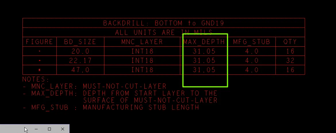
Strict requirements for back drill
If the call proceeds without that confirmation, the second pass may enter the last connected layer and open or damage the inner connection, or it may stop short and leave a longer stub than the note specified. That is the manufacturing reason for the question. It is separate from whether back drilling in PCB is an available process, and separate from substituting a blind via.
Stackup enters this review only as the thickness construction used to set depth. Inner-layer residual copper and a later press figure that replaces a confirmed construction remain stackup topics, except for values already printed on the drawing in this ZIP.
The backdrill file is compared with the primary plated tool at the same XY, with the start side, with the last connected layer, and with the backdrill diameter when the package names it. Finished thickness and the dielectric above that layer come from the released stackup. The customer then confirms 4 mil, specifies a different remaining stub, or releases those vias without backdrill.
Countersink Depth When Finished Board Thickness Is 0.8 mm
Another package required a PCB countersink. After the requested form was applied to the finished geometry, calculated depth was 0.85 mm ±0.2 mm. The same package specified finished board thickness as 0.8 mm.
The cone occupies Z. A depth band that starts near or past finished thickness leaves limited laminate under the point of the bit. The EQ on that job identified the likely consequences: breakage at the small hole, and copper damage on L1 and L2.
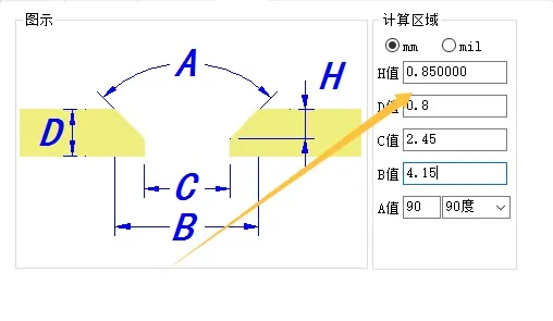
The counterbore hole showed a depth of approximately 0.85mm ±0.2mm
Countersink angle, major diameter, side, and whether the shaft is plated are used when they appear on the drawing. They remain drawing inputs. This article does not present an angle list or a depth-to-thickness fraction as a factory default. The comparison uses the 0.85 mm ±0.2 mm and the 0.8 mm already present in the files.
Copper at the hit affects the close. If L1 or L2 pads or pour lie under the cone, the bit removes that copper. That decision is separate from forming the cone on an empty non-plated hit. The cone is a fastener seat. It is not a stub-removal pass and not an edge bevel on a gold finger.
If the depth band is applied to 0.8 mm stock without confirmation, the point of the bit may break the web at the hole, crack the laminate, or cut outer-layer copper. Finished thickness is compared with sink depth, angle, major diameter, and side, then with L1/L2 copper at that location and with the plating status of the shaft. The customer may change finished thickness, reduce depth, major diameter, or angle so the cone remains within the released thickness, accept or clear the L1/L2 copper removal, or omit the countersink.
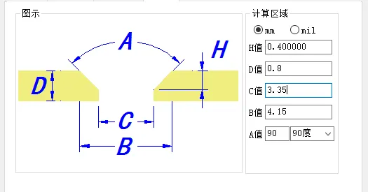
counterbore parameters optimization
Press-Fit Hole Tolerance on Holes Larger Than 2.0 mm
A third package marked press-fit and attached a hole-size tolerance that the factory considered too tight for tools 2.0 mm and above. Alignment and drill-bit error were cited.
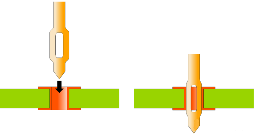
A PCB press-fit hole is a plated barrel whose finished diameter after plating has to match the pin. Fabrication still begins with a drill tool and then includes plating build, wander, and bit wear. Those terms describe the process; they are not offered here as a published tolerance table. Tools 2.0 mm and above appeared in the EQ because the same numeric window is more difficult to demonstrate on a large diameter when registration and bit condition are included. The EQ does not substitute a factory class for the customer window. It asks whether those hits remain press-fit at the released window, become standard plated through holes, or take a different finished size.
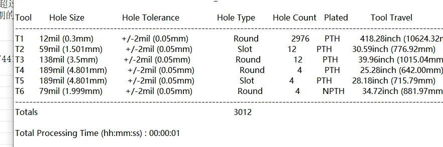
The drilled hole tolerance requirement is too strict. Holes larger than 2.0mm cannot be made as press-fit holes.
Press-fit hole tolerance, in this section, is the window written on the chart. It is not a survey of connector-vendor specifications. A press-fit hole is distinct from an NPTH mounting hole and from a backdrill. If the same barrel also requires stub removal, that is a second process at the same XY and needs its own note.
If the tight window is retained without confirmation, finished size may shift with plating and drill variation, and pin fit will follow that shift. Insertion force is not calculated from the chart during this review. The size class is what the EQ identifies.
The tools labeled press-fit, their chart size, and the tolerance text on that row are identified first, then the plating flag and pad copper at those hits, sufficient to show a plated barrel rather than to score annular-ring width. The customer may keep press-fit and the released window, keep press-fit with a finished-size window they specify, or drop press-fit on the 2.0 mm and above tools and run them as standard plated holes.
Keep the Released Backdrill Stub, Countersink Depth, or Press-Fit Tolerance
The close identifies tools, side, and the value that remains in force. It does not extend one row's decision to every special hole on the board, and it does not replace the released stub, sink depth, or press-fit class with an internal table.
The first option is to retain the released call: the 4 mil remaining stub, the countersink as drawn against 0.8 mm, or the press-fit window on the 2.0 mm and above tools. That option accepts the process risk named in the EQ — stub control relative to the last connected layer, cone geometry relative to finished thickness and L1/L2 copper, or finished size relative to large-tool drill control.
The second option changes the number or the geometry. A different remaining stub replaces 4 mil on the named vias. A shallower or smaller countersink, or a different finished thickness, replaces the 0.85 mm ±0.2 mm band against 0.8 mm. A different finished-hole window replaces the released press-fit tolerance on the large tools. The note and the chart should then carry the agreed value so the earlier figure is not left active beside it.
The third option changes the process on the named hits. Those vias run without backdrill. The fastener hole is drilled through without a countersink. The 2.0 mm and above tools remain plated but are no longer classified as press-fit. After that decision, the hole chart and any backdrill or countersink sketch should identify the same tools. If 4 mil remains on the drawing after a different stub was agreed, if 0.8 mm and 0.85 mm ±0.2 mm both remain active, or if "press-fit" remains on a tool that will run as standard PTH, the package again contains two instructions for the same hits.
Table 3. Named-tool close paths after the EQ.
| EQ scene | Released source | Factory proposal | Close and what changes |
|---|---|---|---|
| 4 mil backdrill stub too strict to control | Drawing or note remaining stub of 4 mil; stackup already in the ZIP | Confirm the stub call | Keep 4 mil remaining stub; name a different stub; or drop backdrill on the named vias |
| Countersink 0.85 mm ±0.2 mm versus finished thickness 0.8 mm | Sink form on the note or sketch; 0.8 mm thickness on the drawing or stackup | Confirm depth; identifies hole break and L1/L2 copper damage | Change thickness; reduce depth, major diameter, or angle; accept or clear L1/L2 copper removal; or omit the countersink |
| Press-fit tolerance too tight on holes 2.0 mm and above | Chart or note press-fit label plus finished-size window on those tools | Window difficult to hold; alignment and drill-bit error | Keep press-fit and the released window; restate the finished-size window; or drop press-fit and run standard PTH |
PCB Backdrilling, Countersink, and Press-Fit Questions From CAM Review
Q1: What is backdrilling in PCB?
A1: A second controlled-depth pass on a plated via that removes unused barrel and leaves a residual stub from the last connected layer. Backdrill is distinct from countersink, from a press-fit class, and from the plated flag on the primary drill.
Q2: What is a residual stub after backdrilling?
A2: The plated barrel remaining after the second pass, measured from the last connected layer. A package that specifies 4 mil is calling that remaining length. Overlay of drill to stackup can identify start side, stop region, and dielectric above that layer. It does not establish the stub that will exist after press and registration.
Q3: What is a typical backdrill stub requirement?
A3: This article does not present a stub capability table. On one job a 4 mil remaining stub was flagged as difficult to control because programmed depth still depends on finished thickness, dielectric above the last connected layer, bit point angle, and registration to the primary hole. Whether 4 mil remains in force is confirmed on that via.
Q4: What is a countersink hole on a PCB?
A4: A conical form at a hole for a fastener head. Depth, countersink angle, major diameter, and side are taken from the drawing or sketch when they are present. The feature is distinct from backdrill and from an edge bevel on a gold finger.
Q5: Can PCB countersink depth exceed board thickness?
A5: A calculated depth of 0.85 mm ±0.2 mm next to a finished thickness of 0.8 mm leaves limited laminate under the point of the bit if both values remain active. That job's EQ identified small-hole break and L1/L2 copper damage. Confirmation then covers thickness, cone size, copper at the hit, or omitting the countersink.
Q6: What is the countersink angle on a PCB drawing?
A6: The included angle of the cone, when the package specifies it. Together with major diameter and depth, it is used to see whether the form fits within finished thickness. No single angle is presented here as factory stock.
Q7: What is a press-fit hole in a PCB?
A7: A plated through hole whose finished size after plating is the interface for a compliant pin. The chart value is that finished-hole window. A plated flag by itself does not classify the hole as press-fit. An NPTH mounting hole is a separate class.
Q8: What is press-fit hole tolerance?
A8: The finished-size window written on the press-fit row of the hole chart or fabrication note. Overlay reads the window and the tool diameter. It does not demonstrate a plated result on every tool. On the EQ that named tools 2.0 mm and above, alignment and drill-bit error were given as the reasons the window would be difficult to hold.
Q9: What hole sizes can be press-fit on a PCB?
A9: This article does not present a maximum press-fit diameter. One package attached a tight finished-size window to holes 2.0 mm and above and asked whether those tools remain press-fit, take a restated window, or run as standard plated holes. Those sizes belong to that EQ.