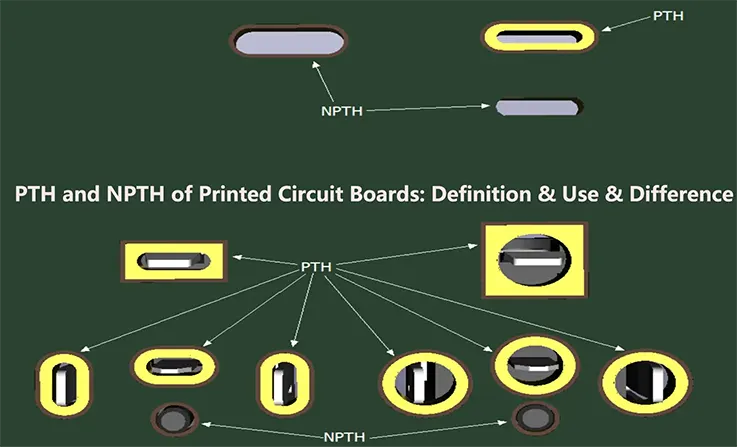
PTH vs NPTH defines whether a through hole is plated. The question usually comes up when the hole chart and the Gerber lands do not describe the same hole, and the plating status has to be resolved before the job runs.
The package already carries that call in more than one file. The hole chart or drill tool list marks each tool PTH or NPTH. Some jobs put a plated column in the Excellon file; others split plated and non-plated hits into two drill files. Outer copper then shows whether those same hits sit on through-hole pads, on an isolated flash, or on bare laminate. Diameter alone, or a pad picture alone, is a weak basis for choosing the barrel.
The reviews that show up tend to look like this. The chart marks a tool NPTH while both outer layers still have pads. Two tools released as plated through holes at 3.2 mm and 6.0 mm come back with a factory request to run them as NPTH, with the stated reason that they cannot be made PTH through aluminum on that job. A highlighted drill matches its pad diameter, no trace leaves the land, and the question is whether those hits should be NPTH. Those three EQs are examples from recent packages, not a full list of how a drill list and a copper file can disagree.
| What the files showed | Where they diverged | What the EQ asked |
|---|---|---|
| Tools at 3.2 mm and 6.0 mm released as plated through holes | Factory states those hits cannot be made PTH through aluminum on this job | Run the named tools as NPTH, or keep them as PCB PTH under a different process arrangement |
| Hole chart marks the tool NPTH; both outer copper layers still have pads | Chart and Gerber lands describe the hole differently | Confirm NPTH as charted, or PTH to match the lands |
| Highlighted drill the same size as the pad; no trace leaves the land | That geometry can be leftover CAD, a mechanical hole, or a land drawn undersize | Confirm NPTH, including whether the flash is removed, or keep PTH and correct the land |
Via tenting, resin plug, tooling holes, and stamp-hole rows belong in their own reviews. This article is limited to the plated flag on a through hole, PCB PTH versus PCB NPTH, and the through-hole pad that may sit on that hit.
PTH vs NPTH in the Released Drill Chart and Gerber
The PTH or NPTH attribute is already defined in the released drill data. We check the tool number, finished size as written, PTH or NPTH attribute, and whether the job uses one drill file or separate plated and non-plated files. A fabrication note may repeat that information or conflict with it.
Those sources can diverge before anyone measures a pad. One file says plated, the chart says NPTH, and the note is silent. PCB Hole size is a poor classifier. A 3.2 mm tool may be a clearance NPTH for hardware, or a plated through hole that carries a net. The same is true of 6.0 mm. Size identifies the tool; it does not, by itself, classify the hole as PCB PTH or PCB NPTH.
We then check the copper against that drill classification. The pads provide supporting evidence; they do not replace the released PCB hole attribute.
PCB Hole Plating and Through-Hole Pads on the Drill Overlay
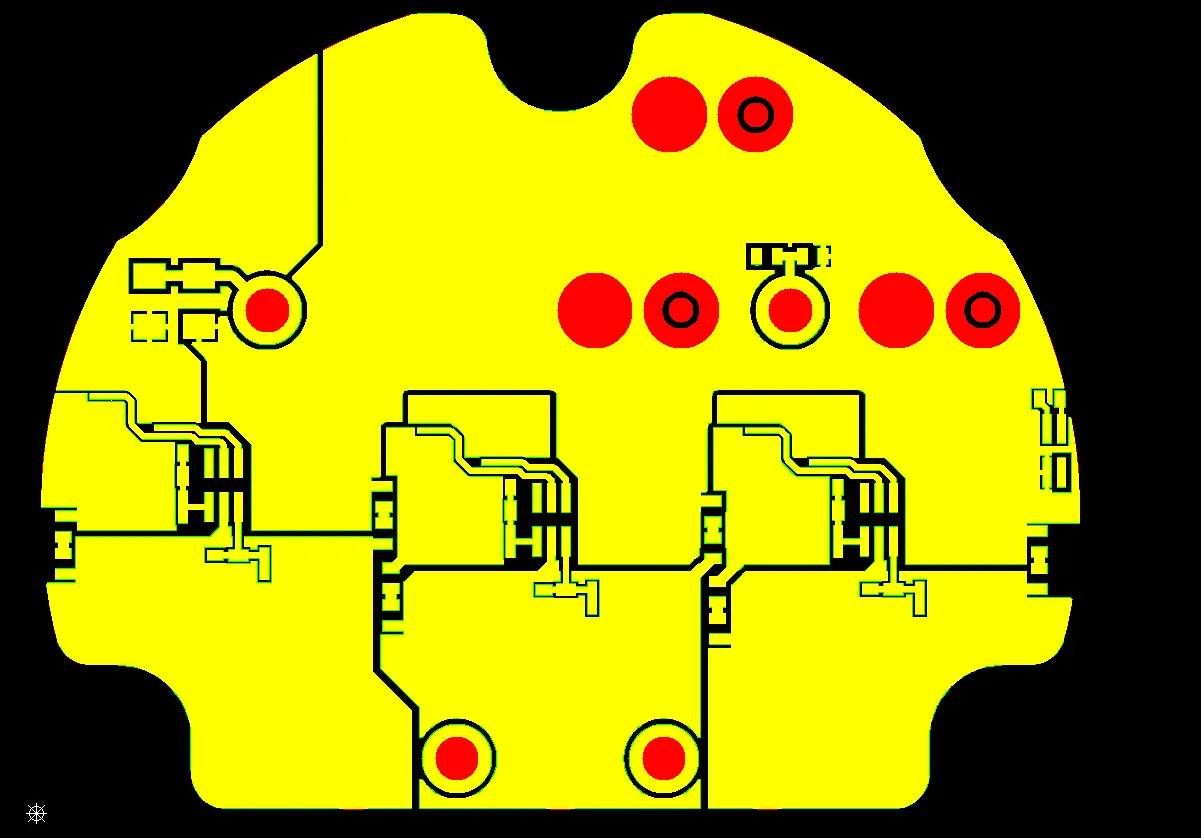
Once the flag is agreed, a PTH hit enters the plating process and forms a plated copper barrel. An NPTH hit is held out of plate, so An NPTH hit is excluded from the plating process, so no plated copper barrel is formed on the hole wall. Overlaying the drill on the copper layers records what copper is present. It does not, by itself, choose the flag.
The overlay is good for a limited set of facts. A through-hole pad is present or absent on top, bottom, or both. The pad is larger than the drill, equal to it, or smaller. A trace leaves the land, the land sits in a plane, or the flash is isolated. Solder mask may be open over the hole or covering it. None of those observations establishes the PTH or NPTH attribute in the drill data.
They also leave several questions open: whether an isolated land is leftover CAD, and whether a large tool still needs a plated barrel because hardware grounds through it. Pads on both outers are consistent with a plated through hole. They also appear on NPTH mounting footprints that the CAD library still exported. Overlay supports the discussion. The written confirmation still has to name PTH or NPTH.
| Overlay can measure | Overlay leaves open | Still needs a written call |
|---|---|---|
| Pad present or missing on top, bottom, and inner layers | Intended PTH vs NPTH flag | Which source to follow: hole chart, plated column, or copper lands |
| Pad diameter versus drill diameter | Plating sequence, and how finished size is read after plate | Whether finished size stays as charted once the flag changes |
| Trace leaving the land, plane membership, isolated flash | Whether an isolated land is leftover CAD or a land drawn undersize | Keep the pad, remove the pad, or redraw a usable ring |
| Mask open or covering the hit | Whether a large tool still needs to remain PTH for hardware ground | Accept NPTH on the named tools, or keep PCB PTH |
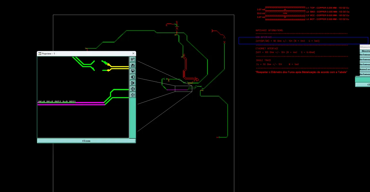
For each disputed tool we compare drill, top pad, bottom pad, inner land, and net. That comparison is what the next three EQs rest on. It still leaves a customer confirmation before the barrel is plated or left bare.
3.2 mm and 6.0 mm Plated Through Holes Proposed as NPTH
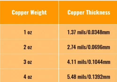
In that job the released tools at 3.2 mm and 6.0 mm were flagged as plated through holes. The factory stated that those hits cannot be made as PTH through aluminum on this construction and proposed to run them as NPTH. That process reason belongs to that EQ and reflects a 2-layer 3 oz aluminum PCB DFM consideration. It is not treated here as a maximum PTH size, and it is not expanded into an aluminum-board tutorial.
Changing PTH to NPTH removes the plated barrel. If either tool carried a net or tied layers together, that connection is lost. If the hole was mechanical from the start, NPTH may already have been the intent and the plated column the error. NPTH hole with pad conflict can also affect the finished-size interpretation. A PTH finished size is the opening after hole plating. An NPTH finished size sits closer to the drilled opening. Compensation is not invented and placed on the traveler as if the drawing had specified it.
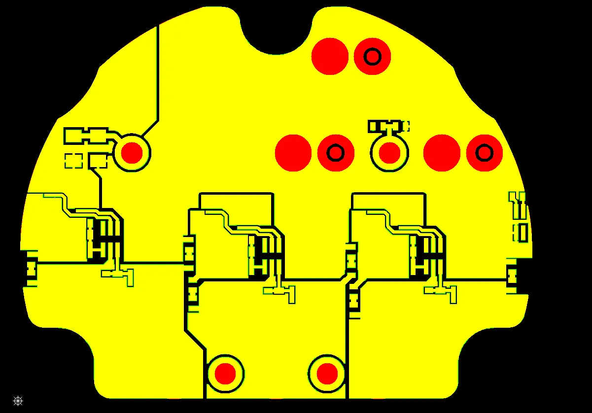
Treating 3.2 mm and 6.0 mm holes as NPTH holes
Those two tools still need an overlay before the proposal is treated as a drill-file correction. Pads or a net on 3.2 mm or 6.0 mm make the NPTH request a design change. The customer either accepts NPTH on the named tools, no barrel copper, and pad removal if that is part of the same confirmation, or keeps PCB PTH and a different process arrangement for those two sizes. Until that confirmation is written, the released plated flag on 3.2 mm and 6.0 mm remains as drawn.
Non Plated Through Hole on the Chart With Pads on Both Sides
This package already contains two instructions. The hole chart marks the highlighted tool NPTH. Both outer copper layers still have through-hole pads on those hits. Overlay shows the pads. It does not decide which instruction prevails.
If the chart is followed, the hole is mechanical NPTH and the barrel stays unplated. The pads may be leftover footprint copper from the CAD library. That close still leaves a second question: leave the pads as drawn, or remove them so an unplated hole is not sitting in a solderable land. This NPTH pad conflict still needs clarification before the hole can be closed. If the pads are followed, the hole is a plated through hole and the hole-chart column is the item that changes. The tool then moves onto the plated drill file.
Pads on both sides are a weak automatic PTH call. Many NPTH mounting footprints still export lands on top and bottom. Following only the copper plates a hole that was meant to stay insulating. Following only the chart, while a net is present, leaves a soldered or grounded hole without barrel copper. Either reading changes how the hole is built. The highlighted tool is matched to the Excellon flag and to top, bottom, and inner lands and nets, then closed as NPTH as charted or as PTH to match the lands.
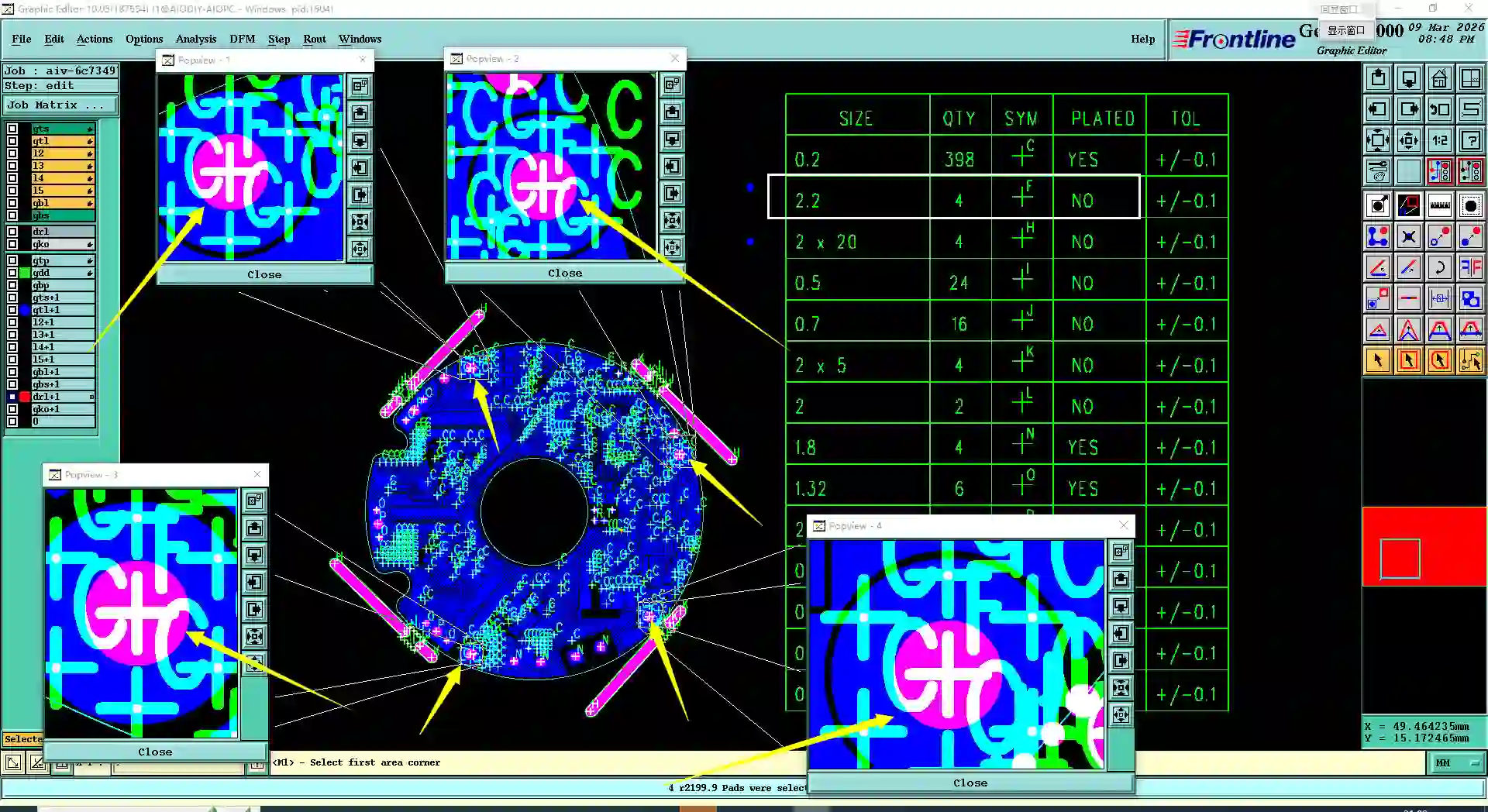
The Non-plated Through holes (NPTH) in the drill file have pads on both sides
Through-Hole Pad the Same Size as the Drill With No Trace
The third EQ highlighted hits whose through-hole pad diameter equals the drill, with no trace leaving the land. That geometry is often read as NPTH. It supports more than one reading: an unused PTH footprint the CAD tool left behind, a mechanical NPTH that still carries a same-size copper flash, or an intended plated through hole whose land was drawn too small to leave a usable ring after drill. These are hole attribute conflicts that need to be checked against the actual pad and drill data.
The absence of a visible spur is not the same as the absence of a net. The pad can sit inside a plane and still be electrical. Equal pad and drill diameters are not treated here as an annular-ring rule, and no minimum ring is published from this review. Pad versus drill is measured, then plane and net membership are checked. The written options stay narrow: NPTH and remove the flash, or keep PTH and correct the land so the plated through hole has copper to plate to. Diameter alone is a thin basis for choosing among those three intents.
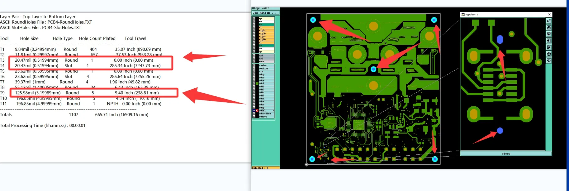
Pad size matched the drill diameter exactly, with no connecting traces
Keep the Released PTH vs NPTH Call or Confirm Hole Plating
The close names tools. Similarity on one row is a weak reason to rewrite every hole on the board.
Keep the released call. Chart NPTH remains NPTH. Chart PTH remains PTH. The 3.2 mm and 6.0 mm tools remain plated through holes if that is how they were released. Isolated same-size pads stay with the flag already on the drill list. Pads that arrived with an NPTH chart stay or come off only when that package already said so.
Accept NPTH on the named tools. The 3.2 mm and 6.0 mm hits, or the pad-equals-drill hits in that EQ, become non plated through hole. The customer accepts the absence of barrel copper. Pad removal, if it follows, is part of the same confirmation. Finished size is then read as NPTH rather than as a plated opening.
Restore PTH to match copper. Chart-NPTH tools that carry through-hole pads and a net become plated through hole. Isolated lands that need to remain electrical keep PTH and a usable land, rather than a flash the same size as the drill. The hole chart and the plated column are corrected to that flag.
A mixed close is available when the EQ names the tools. After the flag is fixed, plated and non-plated drill are split so plate sees one list and the unplated hits remain off it. Pad keep or pad removal travels with the same written line. That close is specific to the named tools; it is not treated as a default size change for the next job.
Table 3. Named-tool close paths after the EQ.
| EQ scene | Released source | Factory proposal | Close and what changes |
|---|---|---|---|
| 3.2 mm and 6.0 mm cannot be made PTH through aluminum | Those two tools flagged as plated through holes | Run the named tools as NPTH | Keep PTH under another arrangement, or accept NPTH: no barrel, NPTH finished size, pad removal if agreed |
| Chart NPTH; pads on both outer layers | Hole chart NPTH versus Gerber through-hole pads | Confirm hole attribute | NPTH as charted, with pads kept or removed, or restore PTH and move the tool to the plated drill list |
| Pad equals drill; no trace leaving the land | Geometry and a missing spur; flag may still be PTH | Confirm whether to make NPTH | NPTH and remove the flash, or keep PTH and redraw a usable land. Diameter is supporting evidence, not the close |
Plate or non-plated on a disputed tool waits on that written line. Until then the released PTH vs NPTH call remains as drawn.
FAQ
Q1: What is the difference between PTH and NPTH?
A1: PTH, or plated through hole, is a hole whose barrel is plated so layers can connect through it. NPTH, or non plated through hole, is held out of plate, so the wall remains laminate. The distinction is the plated flag on the hole chart or drill file, more than the hole diameter.
Q2: What is a plated through hole in a PCB?
A2: A through hole that enters the plate sequence and finishes with copper in the barrel. On the package it is the tool marked PTH. Pads on the outer layers often sit on that hit; the pads are supporting geometry, not the flag.
Q3: What is a non plated through hole?
A3: A through hole left out of plate. Mounting holes, clearance holes, and some hardware holes are released this way. They can still carry copper pads in the Gerber if the footprint was exported with lands. That is why a chart-NPTH tool with pads on both sides is sent back for confirmation.
Q4: What is PCB hole plating?
A4: Copper deposited in the barrel of a PTH. NPTH hits are kept off that sequence. Overlay of drill to pad shows copper around the hole. It does not, by itself, decide whether the barrel should be plated.
Q5: What is a through hole pad?
A5: The copper land at the drill hit. When the pad is larger than the hole it leaves an annular ring. Pads on both outers are consistent with PCB PTH, and they also appear on NPTH mounting footprints. A pad the same size as the drill is still a land in the file. Equal diameters are a weak reason, on their own, to drop plating.
Q6: Why does CAM ask to confirm PTH vs NPTH?
A6: The hole chart and the copper often describe the hole differently, and plate versus non-plated has to be chosen before the job runs. Typical questions are whether to keep the chart, follow the pads, accept NPTH on named tools such as 3.2 mm and 6.0 mm, or redraw a land that is the same size as the drill.
Q7: Can an NPTH hole have pads on both sides?
A7: Yes. That case appears often. The chart said NPTH and both outer layers still had lands. The written close either keeps NPTH as charted and decides whether those pads stay, or restores PTH so the lands and the barrel match.
Q8: Does a pad the same size as the hole mean NPTH?
A8: Equal diameters support more than one reading: leftover PTH footprint copper, a mechanical NPTH flash, or an intended plated through hole whose land was drawn undersize. The pad can also sit in a plane with no spur drawn. Pad versus drill is measured, the net is checked, and the close is written as NPTH with the flash removed, or PTH with the land corrected.
Q9: Who decides PTH vs NPTH when the chart and the copper disagree?
A9: The customer, in a written close that names the tools and whether pads stay or come off. We record the released flag, the overlay at each disputed hit, and the factory proposal. 3.2 mm or 6.0 mm are not flipped to NPTH, a chart-NPTH tool is not plated, and an isolated flash is not stripped, without that line. Until it is written, the released PTH vs NPTH call and the released through-hole pads remain as drawn.