Displacement sensors convert mechanical motion or position into electrical signals for measurement, control, and monitoring. They enable precise quantification of linear or angular displacement, vibration, deformation, and related physical quantities that are otherwise difficult to capture directly. In industrial environments, these sensors support automation, quality control, and condition monitoring across machine tools, automotive systems, aerospace equipment, and electronics manufacturing.
Overview of Measurement Approaches
Displacement sensing methods are broadly divided by scale. Small-displacement applications commonly employ strain gauges, inductive sensors, linear variable differential transformers (LVDTs), eddy-current probes, and Hall-effect devices. Larger strokes rely on resolvers, optical encoders, capacitive scales, magnetic linear scales, and magnetostrictive transducers. Selection depends on required accuracy, environmental conditions, speed, and whether contact or non-contact operation is preferred.
Classification by Operating Principle
Potentiometric Displacement Sensors
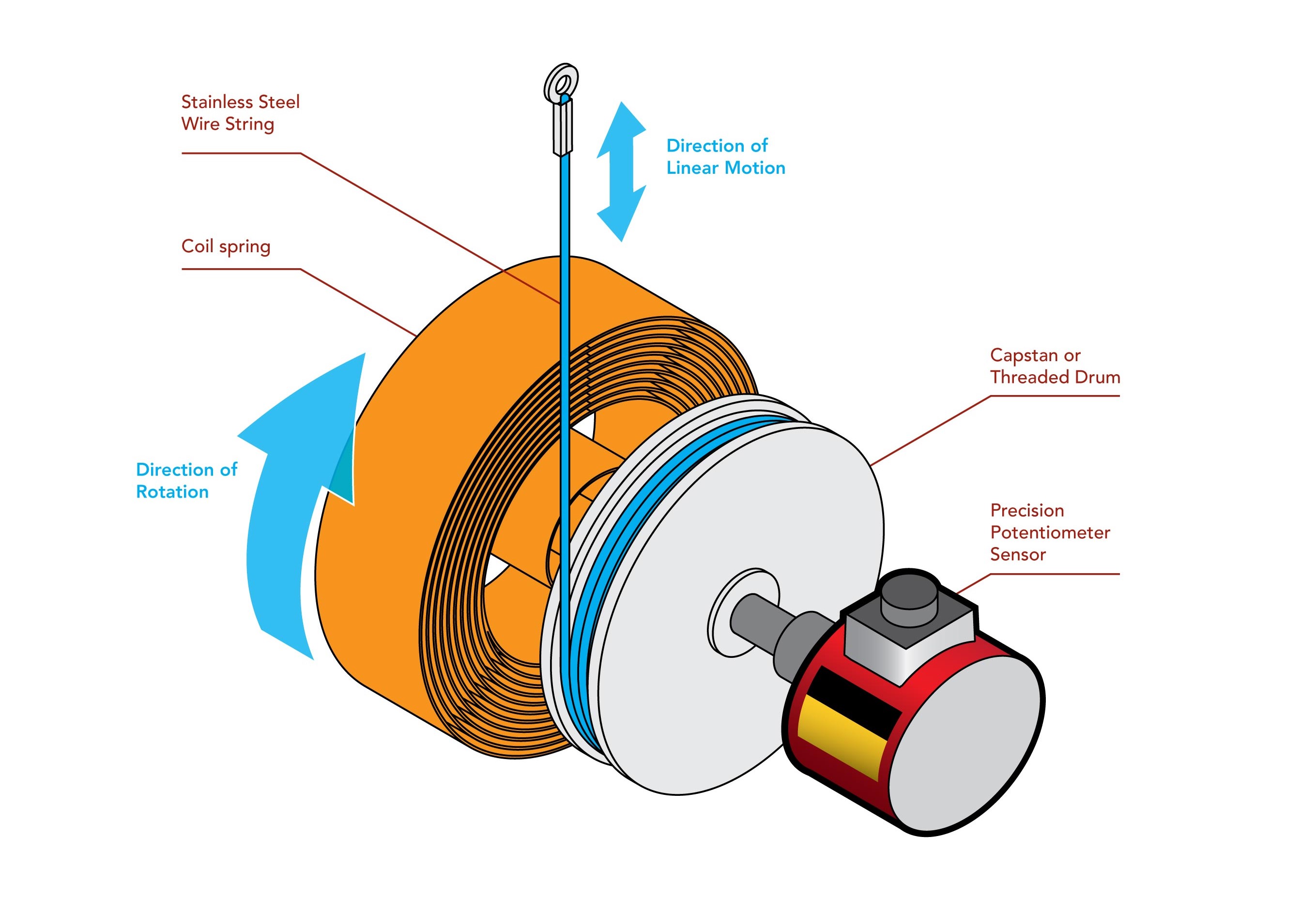
These devices use a resistive element and movable wiper to produce a voltage or resistance output proportional to position. Linear potentiometers measure straight-line travel; rotary versions handle angular displacement. Wire-wound types offer simple construction and low cost but exhibit stepped output and mechanical wear. Conductive-plastic and thick-film (metal-glass) variants improve resolution and durability, while metal-film elements deliver low noise and good temperature stability. Contact-based operation limits life in high-cycle applications and introduces sensitivity to contamination and temperature drift.
Magnetostrictive Displacement Sensors
Magnetostrictive sensors provide absolute, non-contact position measurement using the waveguide principle. A current pulse generates a magnetic field that interacts with a movable magnet ring, producing a torsional strain wave whose transit time yields position data. Typical performance includes 0.05 % F.S. accuracy (0.02 % F.S. on longer strokes) and repeatability to 0.002 % F.S. Advantages include immunity to power loss, long stroke capability (up to several meters), and robustness in oil, dust, and vibration. Limitations include susceptibility to external magnetic fields and incompatibility with nearby ferromagnetic materials.
Optical Encoder (Grating) Sensors
Optical encoders detect displacement via interference or moiré patterns formed by overlapping scale and index gratings. Transmissive and reflective configurations support high-resolution linear and rotary measurements. Digital pulse output enables direct integration with controllers. Strengths include wide range and sub-micron accuracy; constraints involve speed limits (typically <1.5 m/s) and the need for clean optical paths.
LVDT Sensors
An LVDT comprises a primary coil and two secondary coils wound on a non-magnetic form. Core displacement modulates the differential output voltage, which is conditioned to standard analog (0–10 V, 4–20 mA) or digital protocols. Non-contact operation yields excellent linearity, repeatability, and dynamic response. Rugged versions withstand shock, vibration, high temperature, and radiation. Stroke length above approximately 1 m increases manufacturing complexity and can affect linearity.
Eddy-Current Displacement Sensors
These inductive sensors measure the gap between a conductive target and the probe face by detecting changes in eddy-current losses. They deliver high-resolution, high-bandwidth readings on both ferromagnetic and non-ferromagnetic metals, making them ideal for vibration monitoring of rotating machinery. Non-contact operation and tolerance to dust and humidity support online condition monitoring, though non-metallic targets cannot be measured.
Capacitive Displacement Sensors
Capacitive probes sense changes in capacitance between plates separated by air or dielectric materials. They excel at sub-micron measurements in clean or controlled environments and maintain performance under extreme temperatures or radiation when appropriate dielectrics are selected. Range is typically limited to tens of millimeters; electromagnetic interference and parasitic effects require careful shielding and signal conditioning.
Hall-Effect Displacement Sensors
Hall sensors exploit the Hall voltage generated in a semiconductor element placed in a magnetic field gradient. Linear versions measure distance or small displacements; switch-type versions provide position or limit detection. Low power consumption, small size, and fast response suit automotive and industrial position sensing. Temperature compensation and bridge circuitry improve stability.
Ultrasonic Displacement Sensors
Ultrasonic transducers measure time-of-flight of acoustic pulses reflected from the target. They provide non-contact level and distance measurement even in the presence of foam or agitated surfaces when advanced signal processing is applied. Environmental factors such as temperature, humidity, and air turbulence affect accuracy and limit use in harsh or high-speed scenarios.

Classification by Motion Type
Linear displacement sensors track straight-line motion and are commonly implemented as potentiometric, LVDT, or magnetostrictive devices. Angular displacement sensors monitor shaft or wheel rotation and are frequently realized with encoders, resolvers, or Hall-effect elements. Both categories appear in feedback loops for motion control and obstacle detection.
Engineering Selection Criteria
Key parameters include sensitivity, zero-point temperature drift, bandwidth, output format (analog versus digital), measurement range, overload capability, and required signal conditioning. Environmental factors—temperature extremes, vibration, contamination, and electromagnetic interference—must also be evaluated. For high-reliability systems, redundancy, self-diagnostics, and calibration stability become critical.
Integration with Electronic Systems and PCB Technologies
Displacement sensors rarely operate in isolation. Their analog or digital outputs require signal conditioning, filtering, and interfacing circuitry typically implemented on printed circuit boards. PCB layout must address noise immunity, grounding, and thermal management, especially when high-resolution analog signals or high-speed digital protocols are involved. Flexible PCBs enable compact sensor packaging in confined spaces or moving assemblies. High-density interconnect (HDI) technology supports miniaturization of multi-channel sensor interfaces, while material choices such as low-loss laminates and controlled-impedance traces preserve signal integrity. Thermal vias and appropriate copper weights help manage heat in power-hungry conditioning circuits. Reliability engineering practices—conformal coating, robust connector selection, and accelerated life testing—ensure long-term performance in industrial environments. These considerations directly influence measurement accuracy, system uptime, and total cost of ownership in precision manufacturing and automation equipment.
FAQs
Q1: What is the difference between contact and non-contact displacement sensors?
A1: Contact sensors (e.g., potentiometers) rely on mechanical wipers or linkages and offer simplicity but suffer wear. Non-contact types (LVDT, eddy current, optical, magnetostrictive) eliminate friction, extending service life and improving reliability in harsh conditions.
Q2: Which displacement sensor offers the highest accuracy for long strokes?
A2: Magnetostrictive and high-resolution optical encoders typically deliver the best combination of range and accuracy for strokes exceeding one meter, with repeatability often below 0.01 % F.S.
Q3: How do environmental factors affect sensor selection?
A3: Temperature drift, vibration, dust, oil, and electromagnetic interference can degrade performance. Non-contact technologies with appropriate enclosures or compensation circuitry are preferred for demanding industrial settings.