Since the 1980s, Gerber has been one of the de facto formats for transferring PCB manufacturing artwork. The Gerber specification standardizes the content and syntax of fabrication data, not the file names themselves. As a result, different EDA tools output Gerber files with different extensions and naming conventions. This raises a common question: do these suffixes carry special meaning, and do they matter in practical PCB manufacturing workflows?
In short, Gerber file suffixes are not standardized by the format. They exist mainly to help humans and CAM tools identify layers at a glance. Depending on your EDA tool, the suffix may include explicit layer information or use a generic extension. Understanding these conventions can reduce ambiguity, improve communication with your fabricator, and simplify reverse engineering or re-import workflows.
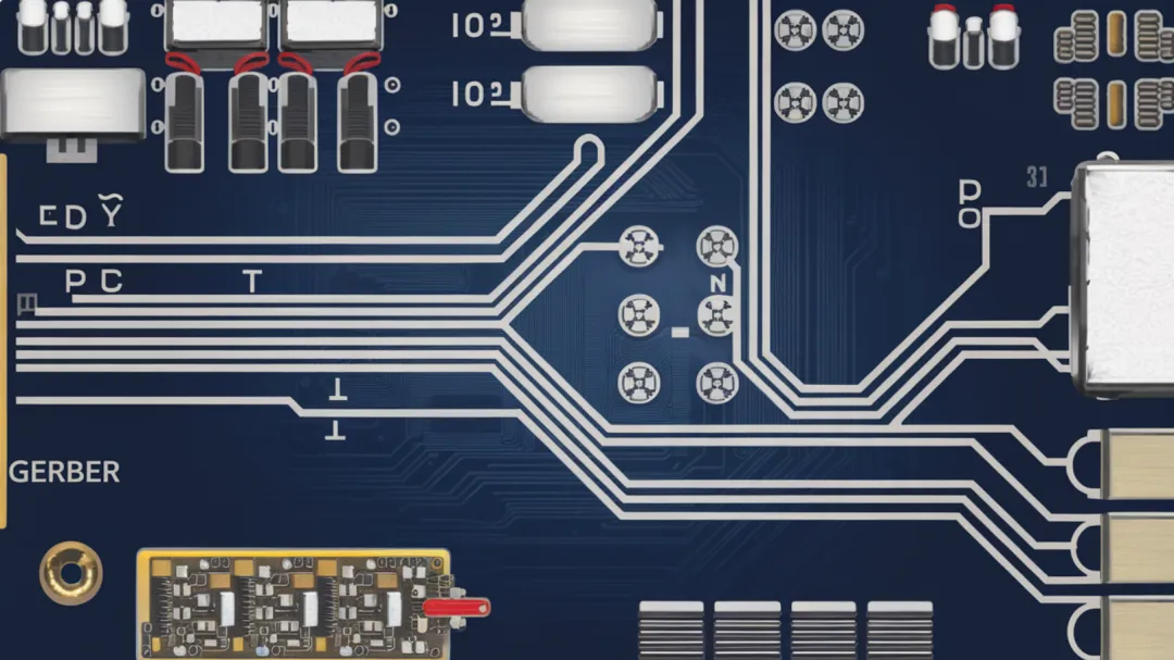
Common Suffixes Used by EDA Tools
Because Gerber does not mandate a filename pattern, a common practice is to use a generic extension such as .gbr. Many EDA tools, however, embed layer information in the filename to make a multi-file set easier to interpret during CAM review or when importing into other tools.
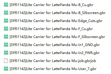
For example, KiCad by default produces filenames that explicitly include the layer name or function, so users and CAM engineers can immediately identify top copper, bottom copper, silkscreen, solder mask, and other layers in the file set.
Gerber is historically associated with photoplotting—creating film artwork for PCB imaging. Reflecting this origin, some tools adopt extensions derived from “photoplot.” For instance, PADS has traditionally used .pho, with sequential numbering for layers (e.g., art001.pho for the first layer, art002.pho for the second), a simple and direct approach.
Cadence Allegro uses .art for all artwork files, borrowing the common industry abbreviation “art” for artwork. This keeps file names short and consistent across layers.
Altium (and legacy Protel) outputs take a different approach and use a family of specific suffixes that encode the layer type directly in the extension. This convention is widely recognized by both CAM tools and engineers and can greatly accelerate layer identification.
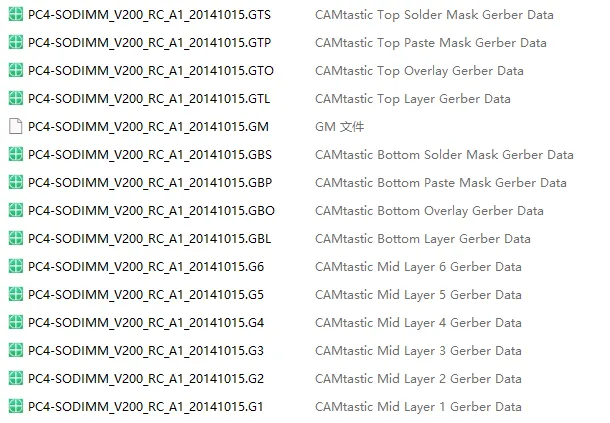
Some fabricators still operate older CAM workflows or maintain settings tuned for specific naming patterns. In such cases, they may request a Protel/Altium-style suffix set for consistency with their processes. To support this, KiCad and other tools can export Gerber files using Protel/Altium suffix mappings without altering the actual data within those files.
It is important to emphasize that changing the suffix does not change the file content. The exported Gerber data remains the same; only the filename is adapted to a requested convention. This flexibility makes it easier to accommodate specific fabricator preferences without regenerating design data.
Meaning of Altium/Protel Gerber Suffixes
The following table summarizes common Altium/Protel-style Gerber suffixes and their meanings. These suffixes help engineers and CAM tools quickly identify the purpose of each file in the fabrication package.
| Suffix | Meaning |
|---|---|
| GTO | Gerber Top Overlay (silkscreen) |
| GBO | Gerber Bottom Overlay (silkscreen) |
| GTL | Gerber Top Signal (top copper) |
| GBL | Gerber Bottom Signal (bottom copper) |
| G1, G2... | Mid Layer 1, 2, ... (inner signal layers) |
| GP1, GP2... | Internal Plane Layer 1, 2, ... (plane layers) |
| GTS | Gerber Top Solder Mask |
| GBS | Gerber Bottom Solder Mask |
| GTP | Gerber Top Paste Mask |
| GBP | Gerber Bottom Paste Mask |
| GKO | Gerber Keepout |
| GM1, GM2... | Gerber Mechanical 1, 2, ... |
| GPT | Gerber Top Pad Master |
| GPB | Gerber Bottom Pad Master |
| PO1 | Gerber Panels (panelization file) |
| TXT | ASCII NC Drill |
| DRL | EIA NC Drill (Excellon) |
| DRR | NC Drill Report |
| APR | Aperture File |
These conventions are particularly helpful when you need to quickly audit a file set, map layers during import, or perform reverse-engineering workflows where Gerber needs to be reconstructed into a PCB project. A clear suffix makes it easy to pair each physical layer with its file, and to separate manufacturing layers like silkscreen, solder mask, and paste stencils.
Gerber X2 and Embedded Layer Attributes
Modern Gerber X2 extends RS-274X by adding standardized attributes that describe file purpose and layer function. With X2, a CAM system can parse layer types, polarity, and other properties directly from the file itself rather than inferring them from the filename. In other words, when you output Gerber X2, the layer stack and functional metadata are embedded in the data stream, reducing ambiguity and the reliance on naming conventions.
In practice, that means fabricators can correctly identify top copper versus bottom copper, paste versus solder mask, and mechanical or keepout layers even if the filenames use generic extensions. X2 attributes help synchronize designer intent with CAM interpretation, improving robustness in multi-tool workflows and lowering the risk of layer swaps or misinterpretation.
Drill, Aperture, and Ancillary Files
Fabrication packages typically include more than just copper and mask artwork. Drill and related files are essential for successful manufacturing:
- TXT (ASCII NC Drill) or DRL (EIA/Excellon NC Drill): defines plated and non-plated holes, tool numbers, and drilling coordinates.
- DRR (NC Drill Report): summarizes drill sizes, counts, and sometimes layer associations, assisting CAM checks and quoting.
- APR (Aperture File): in legacy flows, lists apertures (shapes and sizes) used by Gerber; while RS-274X embeds apertures, some workflows still generate or accept a separate aperture file for compatibility.
These ancillary files complement the artwork and ensure the fabricator has complete information for imaging and machining. Where possible, consistent tool naming, units, and zero-suppression settings should be used across the drill and artwork to prevent misalignment.
Practical Considerations and Best Practices
Because the Gerber specification does not standardize file suffixes, different naming schemes can coexist across EDA tools and fabrication workflows. Practically, the suffixes matter in three common scenarios:
- Human readability and quick validation: clear suffixes make it easy for engineers and CAM operators to verify that all required layers are present and correctly labeled.
- Reverse engineering or re-import: some tools map layers based on filename suffix, so standard suffix conventions reduce manual remapping effort.
- Legacy CAM compatibility: older CAM setups may rely on well-known Protel/Altium suffixes to trigger specific import profiles.
When a fabricator requests a particular naming convention, most modern EDA tools can export using those suffixes without altering the underlying data. If your tool supports Gerber X2, enabling it typically reduces dependence on filename conventions because layer attributes are embedded.
In addition to Gerber, consider richer manufacturing data formats when supported on both sides of the workflow. ODB++ and IPC-2581 carry more manufacturing intent, including stackup, netlists, material properties, and detailed layer mapping. These formats can reduce communication overhead and minimize the risk of misinterpretation, provided your fabricator accepts them.
Conclusion
Gerber file suffixes are not governed by a universal standard and vary across EDA tools. They exist to aid identification rather than to carry machine-enforced meaning. For legacy CAM environments, specific suffixes—often the Protel/Altium conventions—may still be requested. If your toolchain supports Gerber X2, use it to embed layer information directly in the files, reducing the need for external documentation about layer order and purpose.
Where supported, ODB++ or IPC-2581 can provide even richer manufacturing data and further lower the communication barrier between design and fabrication. Ultimately, whether you rely on traditional Gerber with clear suffixes or migrate to X2 and data-rich formats, the goal is the same: unambiguous, complete, and process-ready manufacturing data.