FR4 PCB Return Path Design: Avoiding Signal Integrity Problems
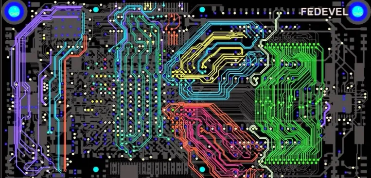
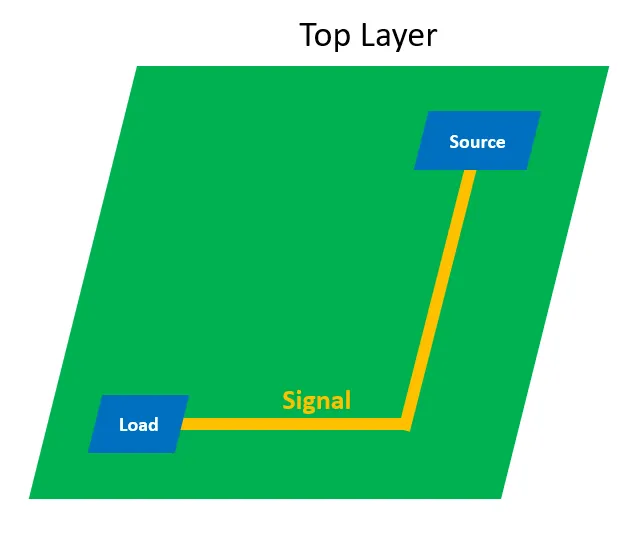
FR4 PCB return path is the copper under the trace, not the GND symbol. Plane splits, missing return vias, and layer hops open the loop and break SI.
Printed Circuit Board (PCB) design forms the backbone of modern electronics, enabling the creation of compact, efficient, and reliable devices that power everything from smartphones to industrial machinery. In this category, readers gain access to a comprehensive collection of resources dedicated to mastering PCB design principles and techniques. Whether you are a seasoned engineer refining complex layouts or a newcomer learning the fundamentals, these articles provide the knowledge needed to tackle real-world challenges in electronics development. The scope of PCB design covered here extends from initial schematic capture to final board fabrication and testing. Articles delve into essential topics such as layer stacking, signal integrity, thermal management, and component placement strategies. Guides and tutorials offer step-by-step instructions for using popular software tools like Altium Designer and KiCad, while insights explore emerging trends like flexible PCBs and high-speed designs. Best practices emphasize error reduction, cost optimization, and compliance with industry standards, ensuring designs are not only functional but also manufacturable at scale. Real-world applications highlight the category's practical value, demonstrating how effective PCB design contributes to innovations in automotive systems, medical equipment, renewable energy solutions, and consumer gadgets. By addressing common pitfalls and sharing expert tips, these pieces equip professionals to enhance product performance and reliability. Readers benefit from building a deeper understanding through interconnected articles that cover foundational concepts alongside advanced methodologies, fostering continuous improvement in electronics projects. For those involved in prototyping or production, the technical relevance of this content lies in its focus on efficiency and innovation. Detailed discussions on impedance control, EMI shielding, and design for manufacturability prepare you to meet the demands of today's fast-paced tech landscape. Engaging with multiple articles in this category allows for a progressive learning path, where foundational knowledge supports exploration of specialized topics, ultimately leading to more robust and innovative PCB designs.
FR4 PCB return path is the copper under the trace, not the GND symbol. Plane splits, missing return vias, and layer hops open the loop and break SI.
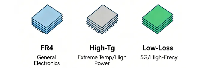
FR4 vs high speed PCB material compared from the fab floor: Dk/Df, insertion loss, frequency range, impedance control, cost, and when FR4 high frequency PCB builds still make sense.
How an FR4 PCB reference plane sets return current for high-speed nets—why plane splits break Z0, and how to keep the plane continuous in layout.
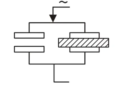
FR4 Dk sets delay and impedance. Df sets loss. Why the 1 MHz datasheet pair fails at GHz, and what to put on the stack note instead of "Dk 4.5."
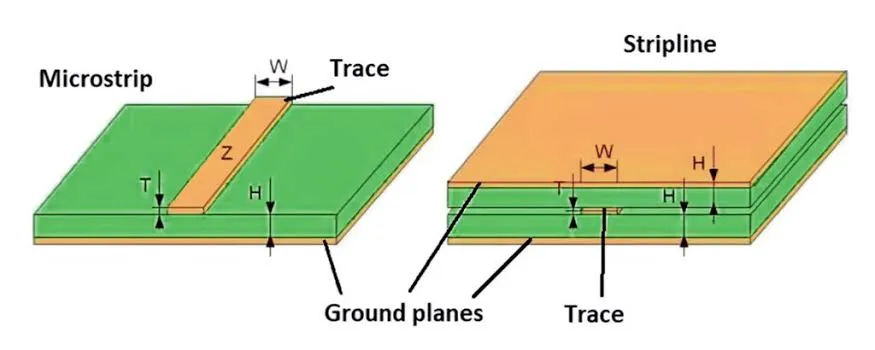
FR4 PCB impedance tolerance is a coupon window, not CAD accuracy. When ±10% is enough, when ±5% fails on outer microstrip, and how Dk, prepreg, etch, and mask spend the budget.
When FR4 PCB controlled impedance is actually required: which high-speed nets need a target Z0, why a 1.6 mm two-layer stack cannot hit 50 Ω at signal widths, and how fab meets the number with stackup, etch compensation, and coupons.
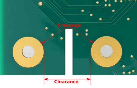
FR4 PCB creepage vs clearance are not the same spacing rule. Set creepage and PCB clearance high voltage from working voltage, CTI, and pollution degree—not one CAD gap.
Learn when FR4 PCB length matching is required based on propagation delay. Covers interface tolerances, serpentine design rules, and practical PCB trace length matching guidelines for high-speed signals.
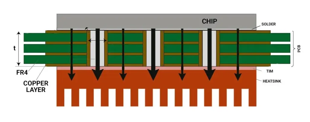
Practical FR4 PCB thermal via design for high-power components. Covers heat path, optimal via count, pitch limits, copper plane continuity and thermal resistance optimization to avoid overheating on standard FR4 boards.
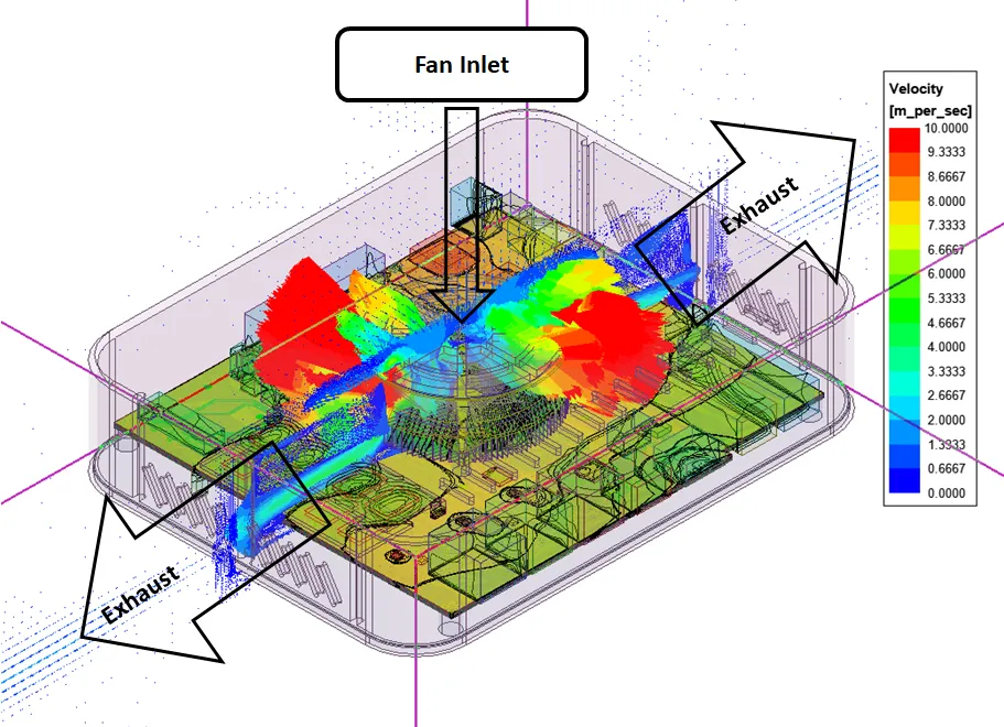
Learn FR4 PCB component placement thermal rules: identify heat sources, set spacing, build copper spreading paths, and place high-power parts without hot islands. Practical PCB thermal component placement guidance.
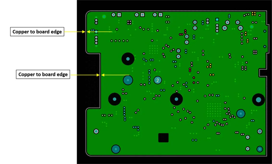
FR4 PCB edge clearance defines how far copper must stay from the finished board edge. Covers routing tolerance, exposed-copper shorts, depanel stress, and safe copper-to-board-edge spacing on standard FR4.
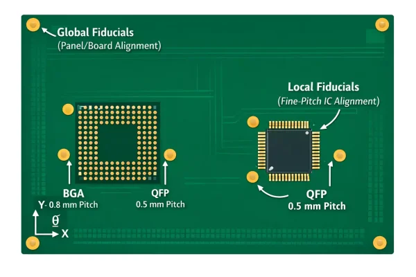
Learn FR4 PCB fiducial design rules for reliable SMT: global vs local marks, size and clearance, camera recognition, and PCB fiducial placement errors that cause misalignment.