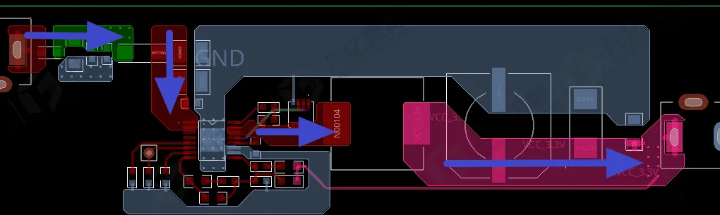
Module reuse in PCB design is a practical engineering approach that captures a proven circuit as a reusable schematic and layout block. Instead of redoing the same work across projects and product variants, teams package stable functions—such as power rails, sensor interfaces, or memory channels—into reusable modules that include their schematics, PCB placement and routing patterns, constraints, and documentation. When executed well, module reuse shortens design cycles, reduces human error, preserves signal and power integrity practices, and increases the likelihood of first-pass success.
What Is a Reusable PCB Module?
A reusable module is a self-contained functional block with a clear interface. At the schematic level, the module is typically delivered as a hierarchical block or design snippet with standardized ports and optional parameters. At the PCB level, it includes a placement pattern, routing topology, keep-in/keep-out regions, stitching and return-path features, and constraint templates. A robust module also includes associated libraries (symbols, footprints, 3D models), manufacturing notes (assembly orientation, test points), and assumptions (stack-up, impedance targets, power rails, and environmental requirements).
Two complementary forms of reuse exist:
- Schematic reuse: Reusing a captured circuit, including parts, connectivity, and annotations, often parameterized so the same block can adapt to different power levels, interface widths, or options.
- Layout reuse: Reusing the placement and routing pattern of a validated block, often with preserved constraints such as differential-pair rules, length matching, clearance rules, and return-path provisions.
Why Reuse PCB Modules?
Effective reuse offers benefits that go beyond productivity:
- Consistency: Proven placement and routing patterns, decoupling networks, and constraints are consistently applied, reducing variability across projects.
- Signal and power integrity: The reused block encodes SI/PI practices—trace impedance, differential pair constraints, return-path continuity, decoupling placement—that have been validated by simulation or measurement.
- Reduced risk: Known-good patterns lower the risk of regressions and shorten the learning curve for new team members.
- Faster ECOs: Changes to a module propagate predictably, and the impact area is constrained, making engineering change orders easier to manage.
- Testability and manufacturability: DFM/DFT considerations are baked in, preserving test-point strategies and assembly guidance across designs.
Typical Candidates for Reuse
Not every circuit is a good candidate for reuse. Choose blocks that are functionally stable and well-understood, where success depends on consistent detail rather than one-off optimization:
- Power delivery modules: DC-DC converters, LDO rails with associated filtering, sense resistors, and thermal features.
- Clocking modules: Oscillators and PLL buffering with controlled ground return and isolation keepouts.
- High-speed interfaces: Memory channels, serial links, and parallel buses where placement, topology, and length matching are critical.
- Connectivity: USB, Ethernet PHY-to-MAC interfaces, common connector pinouts, and ESD protection networks.
- Analog front-ends: Sensor inputs with anti-aliasing filters, shielded return paths, and guarded placement regions.
- Embedded controllers: MCU plus boot mode circuitry, programming headers, and reset supervision.
How to Build a Reuse-Ready Module
1. Define the Electrical Interface
Clearly capture the module's signals, power rails, grounds, and references. Use named, typed ports for clocks, resets, differential pairs, and sensitive nodes. Document signal directionality and any dependency on reference voltages or bias networks. For multi-lane or multi-channel blocks, define ports as vectors with clear indexing.
2. Harden Power Integrity
Include a complete decoupling network with placement constraints and recommended capacitor types. Provide guidance on bulk versus high-frequency decoupling, via count to planes, and return path provisions. If the module assumes a certain plane impedance or target impedance profile, state it and capture the constraints needed to meet it.
3. Lock Symbols, Footprints, and 3D Models
Freeze the symbol and footprint revisions used by the module and record their library sources. Attach 3D models to validate mechanical envelopes. Include assembly notes: orientation markers, polarized components, height restrictions, and any rework access preferences.
4. Encode Constraints Inside the Module
Capture routing and placement constraints with the module, not scattered across the host design. Include:
- Net classes and differential-pair definitions
- Impedance and width rules for controlled lines
- Clearance rules around sensitive areas (e.g., keepouts for oscillators or antennas)
- Length matching groups and skew constraints
- Via rules (drill sizes, via types) and stitching recommendations
Parameterize where reasonable. For instance, allow a user to select a target impedance, and derive widths and spacings from the project's actual stack-up.
5. Capture Layout as a Reusable Pattern
Place components tightly according to functional proximity and return-path logic. Route critical nets with their intended topology (daisy-chain, point-to-point, or fly-by) and include stitching vias and reference-plane openings as part of the block's geometry. Define keep-in/keep-out rooms around the module, and include mounting holes, shields, or mechanical ties if they are functionally required.
6. Document Assumptions
State the environmental and technological context in which the module has been validated:
- Stack-up assumptions and controlled-impedance layers
- Minimum trace/space, via technology, solder mask type
- Operating frequency ranges and timing margins
- Thermal constraints or heat spreading expectations
These assumptions help users judge when reuse is safe or when the block must be adapted.
Layout Reuse and Replication
Layout reuse is most powerful when a block's placement and routing are directly instantiated in a new design. This is common for multi-channel systems, where a single channel is duplicated N times to ensure symmetry and identical timing. Effective replication preserves:
- Relative placements, including rotations and mirrored instances when allowed
- Critical routing lengths, tuning structures, and pair coupling
- Return-path stitching around edges and apertures
- Local reference plane and via fences
Be cautious when the host board's stack-up or plane allocation changes. A routing shape that achieves a target impedance on one stack-up may not be compliant on another. If the module's controlled lines were sized for a specific dielectric and copper thickness, widths and spacings must be recalculated and, if needed, the route updated rather than blindly reused.
Constraint Reuse and Parameterization
Constraint reuse is often underappreciated. A module should bring along:
- Net naming conventions and mappings, including differential suffixes and vector indices
- Rule sets for width, spacing, neck-down limits, and permitted via counts
- Timing groups with length and skew budgets
Because host projects differ, constraints should be parameterized where possible. For example, define a timing group in terms of allowable skew rather than absolute lengths, and bind the skew to project-specific propagation velocities derived from the stack-up. During integration, ensure net name mapping is unambiguous to avoid mismatched constraint application.
Data Management and Version Control
Reusable modules are software artifacts: they evolve, require versioning, and benefit from traceability.
- Version the module as a unit, including schematics, layout patterns, constraints, and documentation.
- Track dependencies on library items such as symbols and footprints. Reference explicit revisions to avoid silent changes.
- Maintain a change log, including rationale and compatibility notes. Indicate whether a change is backward compatible or requires a revalidation in host designs.
- Bundle a bill of materials with approved alternates and fit-form-function equivalence notes. Capture supply chain risks and preferred substitutions to reduce redesign during shortages.
SI/PI and DFM Considerations When Reusing
Module reuse can encode high-quality SI/PI practices, but only if the block covers the complete context of its electrical behavior:
- Return paths: Include return vias and plane stitching that preserve loop area control for high-speed and sensitive analog paths. If the host assigns different plane layers, document how to reestablish return continuity.
- Reference plane apertures: If the module uses slots or apertures to control coupling, include them in the geometry with associated keepouts and mechanical notes.
- Decoupling: Capture placements with via counts and proximity to pins. Avoid abstract decap "clouds"; specify concrete lattice patterns where necessary.
- EMC/ESD: Preserve component placement for transient suppression and edge-rate control, and include ground stitching that was part of EMC success.
- Testability: Carry test points and access keepouts, including notes on probe access, bed-of-nails compatibility, or boundary-scan use.
- Manufacturing constraints: Ensure the module's trace/space, hole sizes, and copper features comply with the intended manufacturing class. If the host uses different capability limits, highlight which features require adjustment.
A Practical Reuse Workflow
- Select the candidate function after it demonstrates stable performance across at least one production design.
- Refactor the schematic into a hierarchical block with clean ports and documented assumptions.
- Normalize symbol and footprint libraries, lock revisions, and attach 3D models.
- Extract the placement and routing into a reusable layout block. Define a placement "room" and boundaries.
- Attach constraints: net classes, differential pairs, impedance rules, length matching, and via usage.
- Parameterize tunable aspects: target impedances, permitted length mismatches, optional interfaces.
- Create a validation checklist and run it on a test harness board if feasible, confirming SI/PI, EMC, and thermal behavior.
- Package DFM/DFT assets: test points, assembly notes, polarity marks, and inspection guidelines.
- Version the module, publish it to the team library, and provide integration notes with example mappings.
- On each reuse, perform a context review: stack-up differences, mechanical constraints, power budgets, and rule conflicts.
Common Pitfalls and How to Avoid Them
- Net name collisions: If reused net names collide with existing project names, constraints may apply incorrectly. Use clear namespace conventions or enforce mapping during integration.
- Stack-up drift: Controlled-impedance patterns tuned for one stack-up may be out-of-spec on another. Always recompute widths and spaces when the dielectric or copper thickness changes.
- Copy-paste without constraints: Simple copying of copper shapes without bringing associated rules and timing groups undermines reuse quality. Package constraints with the module.
- Hidden assumptions: Unstated dependencies—such as reliance on a nearby plane or specific via fill—can break behavior in the new context. Document assumptions explicitly.
- Overfitting: Some high-speed or RF patterns are tightly coupled to their environment. If a block's behavior is highly context-dependent, consider reuse of the schematic and constraints only, not the layout.
- Library drift: Changing footprints or padstacks without updating the module can introduce manufacturability issues. Freeze and reference explicit library revisions.
When Not to Reuse
Reuse is not universal. Avoid layout reuse when:
- The host design's stack-up or plane assignment materially differs, affecting impedance and return paths.
- The operating frequency, data rate, or timing budget is significantly tighter than the module was validated for.
- The manufacturing class changes—e.g., moving from through-hole vias to HDI microvias or changing minimum trace/space limits.
- Mechanical constraints (heatsinks, shields, enclosures) force major placement changes that invalidate the tuned pattern.
In these cases, reuse the schematic, constraints, and placement guidance, then re-route in-context while preserving the critical behaviors.
Measuring Success
Evaluate reuse programs with engineering-centric metrics: time-to-first-layout for recurring functions, number of SI/PI regressions detected late, ECO count related to reused blocks, and first-pass yield of designs incorporating reusable modules. Continuous measurement helps teams refine modules and identify where reuse delivers the most value.
Module reuse institutionalizes proven design practices and transforms individual experience into organizational capability. By packaging circuits as reusable schematic and layout blocks—with constraints, documentation, and assumptions—teams achieve faster cycles with fewer surprises, while preserving the integrity and manufacturability of high-quality PCB designs.