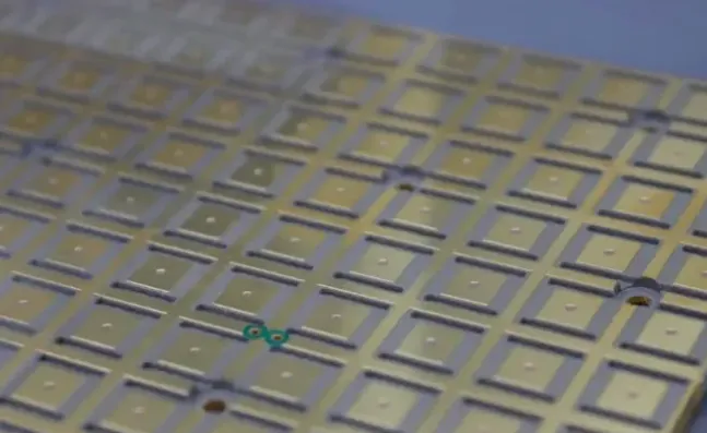
In production we treat every 8-layer job by first locking the stackup against the customer Gerbers and drill file, then applying fixed CAM compensation and panel rules before any material is issued. CAM engineers check layer-to-layer registration targets, copper density balance on every signal and plane layer, minimum trace/space against the etch capability of the finished copper weight, annular ring remaining after drill wander plus registration, and the final pressed thickness window. Those 8 layer pcb dfm guidelines are the baseline we run every panel against; anything that falls outside is either adjusted in CAM or sent back before tooling.

Why 8-layer lamination forces tighter registration and copper control
An 8-layer stack uses multiple cores and prepreg sheets that are pressed in one cycle. Each sheet has its own resin flow and thickness variation; the press platens and pin systems can only hold the layers to roughly ±75–100 µm layer-to-layer under normal conditions. Copper foil also expands differently from the dielectric, so any large imbalance in copper coverage between the outer and inner layers produces differential shrinkage that shifts the registration further after cool-down. Etch undercut on the inner layers is already set by the copper weight and etch chemistry; once the stack is pressed, that undercut cannot be corrected. The same panel must then survive mechanical drilling, where the drill bit walks and the panel expands under heat, eating into the annular ring that was designed on the CAD.
What registration error and copper imbalance do to vias and traces
When registration drifts beyond the allowed window, the drill breaks out of the pad on one or more layers. On an 8-layer board that usually appears first on the inner signal layers where the annular ring was already tight. The result is incomplete plating or an open circuit that only shows up at electrical test, forcing the panel into scrap or selective rework. Uneven copper density creates warpage after lamination; the panel bows enough that the solder-mask printer cannot hold the opening registration and the surface-finish plating thickness varies across the panel. Trace necking from uncontrolled etch undercut on the outer layers reduces current-carrying capacity and can open during thermal cycling. In practice these defects drop first-pass yield and push the shipment by the time the panels are reworked or replaced.
How factories compensate traces, drills and copper before the press
On the CAM side we apply etch compensation to every trace and space according to the finished copper weight and the process capability of the etcher. For 1 oz copper on an 8-layer board the typical compensation is 1–1.5 mil total (half on each side) so the finished width lands inside the customer tolerance after undercut. Spacing is checked against the same etch allowance plus any residual copper that remains between features. Drill files are adjusted for the expected drill wander and the registration tolerance of the stack; we usually require a finished annular ring of at least 5 mil after all process variation for mechanical vias, and we flag any via whose CAD ring falls below that. Microvias and stacked vias are treated separately because their laser or sequential-lamination registration is tighter, but the annular-ring rule still applies to the capture pad.
Copper balance is corrected by adding thieving or dummy copper on the light layers so that the copper coverage on every layer stays within roughly 10–15 % of its neighbors. The thieving is placed outside the active area and is removed or left as non-functional copper depending on the customer's electrical constraints. Panelization is chosen so that the copper distribution remains symmetric across the entire panel; we avoid large open areas on one side of the panel that would drive warpage after press. Board-thickness targets are set by selecting core and prepreg combinations whose pressed thickness, including copper, falls inside the customer's finished-thickness window; we normally hold the pressed stack to ±10 % or better by controlling resin content and press cycle.
Solder-mask openings and surface-finish registration on the outer layers
Solder-mask artwork is compensated for the expected mask swell and the printer registration. We typically open the mask 2–3 mil larger than the pad on each side so that the copper remains fully exposed after the mask shifts. Surface-finish processes (ENIG, HASL, immersion silver) add their own thickness and edge undercut; CAM checks that the finished pad size still meets the assembly requirement after that reduction. These adjustments are locked into the production films before the panel enters the mask room.

File checks that catch the problems before tooling is released
Before any film or drill program is released we verify that the Gerber layers match the supplied stackup, that the drill file accounts for every via type (through, blind, buried), and that the netlist extracted from the Gerbers matches the customer netlist. Copper density is measured on each layer; any layer more than 15 % off balance is flagged for thieving. Minimum trace, space, annular ring and hole-to-hole spacing are run against the factory capability table for the copper weight and board thickness. Stackup thickness is recalculated with the actual core, prepreg and copper values we will use. These checks are the last gate; if they pass, the job moves to production with the compensations already applied.
When the factory relaxes the normal 8-layer rules
On prototype or low-volume runs where the customer accepts higher risk, we can relax annular-ring and copper-balance limits if the design is not impedance-controlled and the panel size stays small. The trade-off is lower first-pass yield and a higher chance of warpage that still needs to be managed at assembly. For high-volume or Class 3 product we stay inside the standard limits because the cost of scrap quickly exceeds the cost of the extra CAM work or a minor layout change.
Conclusion
Designers who follow solid 8-layer PCB DFM guidelines send a stackup that already balances copper within 15%, annular rings that leave at least 5 mil finished after process variation, and trace/space that sit above the etch capability of the copper weight they specify. They also include the netlist and note any controlled-impedance or Class 3 requirements so we do not have to reverse-engineer the intent. When those items are already clean, CAM time drops and the first panel usually passes electrical test without selective rework. Anything left open gets flagged in the DFM report and either adjusted on our side or returned for a layout change before material is released.
FAQ
Q1: How much annular ring do you actually need on an 8-layer board?
A1: We design for a finished annular ring of 5 mil minimum after drill wander and registration. On the CAD that usually means starting with 8–10 mil or more depending on hole size and copper weight. Below that we flag the via because breakout risk rises sharply once the stack is pressed.
Q2: Can you fix copper imbalance in CAM without changing the layout?
A2: Yes, for most boards we add thieving or dummy copper outside the active circuitry. If the imbalance is extreme or the board is impedance-controlled and the thieving would affect electrical performance, we send it back for a layout adjustment instead of forcing the panel into warpage.
Q3: What registration tolerance do you hold on a standard 8-layer press?
A3: Under normal conditions we hold layer-to-layer registration to roughly ±75–100 µm. That number already includes pin stretch, resin flow and cool-down shrinkage. Designs that require tighter registration need sequential lamination or special pin systems and are quoted separately.
Q4: Do you apply different etch compensation on inner versus outer layers?
A4: Yes. Inner layers are etched before lamination and see less undercut once the stack is pressed, while outer layers are etched after plating and usually need slightly more compensation. We set the values from the actual copper weight and the etcher capability table for that job.
Q5: When do you reject a stackup instead of adjusting it?
A5: We reject or return a stackup when the pressed thickness cannot meet the customer window with available cores and prepregs, or when copper imbalance cannot be corrected without violating impedance or clearance rules. In those cases the DFM report lists the exact layers and the required changes before we tool the job.