This article examines the practical effect of placing a glass fiber mesh under a single-sided copper-clad board during chemical etching. The intent is to elevate the PCB slightly above the tank bottom so that fresh etchant can flow beneath the board, improving mass transport to the copper surface. We first document observations with and without the mesh, then explain the mechanisms behind the differences and provide practical guidance for small-scale PCB etching.
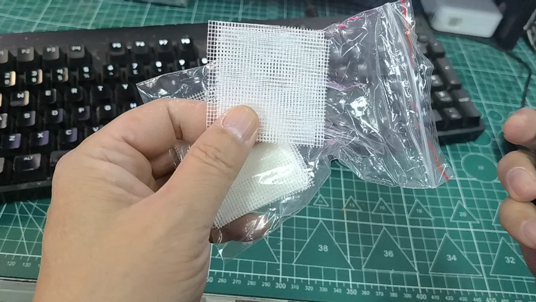
Figure 1 | Glass fiber mesh used as a spacer under the PCB during etching
Experiment Overview
Two identical toner-transferred single-sided copper-clad boards were prepared. The etchant was formed by combining a solid peroxide source with diluted hydrochloric acid in an etching tank. The sequence was:
- Place the glass fiber mesh and the copper-clad board into the tank.
- Add the solid peroxide source and allow it to dissolve.
- Add diluted hydrochloric acid, initiating the etch. The solution quickly turned green, indicating formation of copper chloride as copper dissolved from the board.
- After etching, decant the spent solution and rinse the board with tap water.
A second run without the mesh followed the same steps. Although no timing was recorded, qualitative comparisons were made based on visual observations of etch progress and uniformity.
Observations With the Glass Fiber Mesh
With the mesh placed under the board, the copper-clad panel was raised slightly above the bottom of the tank. This created a clearance for etchant to circulate under the board. The process proceeded smoothly, with the solution visibly active beneath the center of the board.
From a visual, qualitative standpoint, the etching appeared fast and stable. The board was subsequently rinsed with water to stop the reaction.
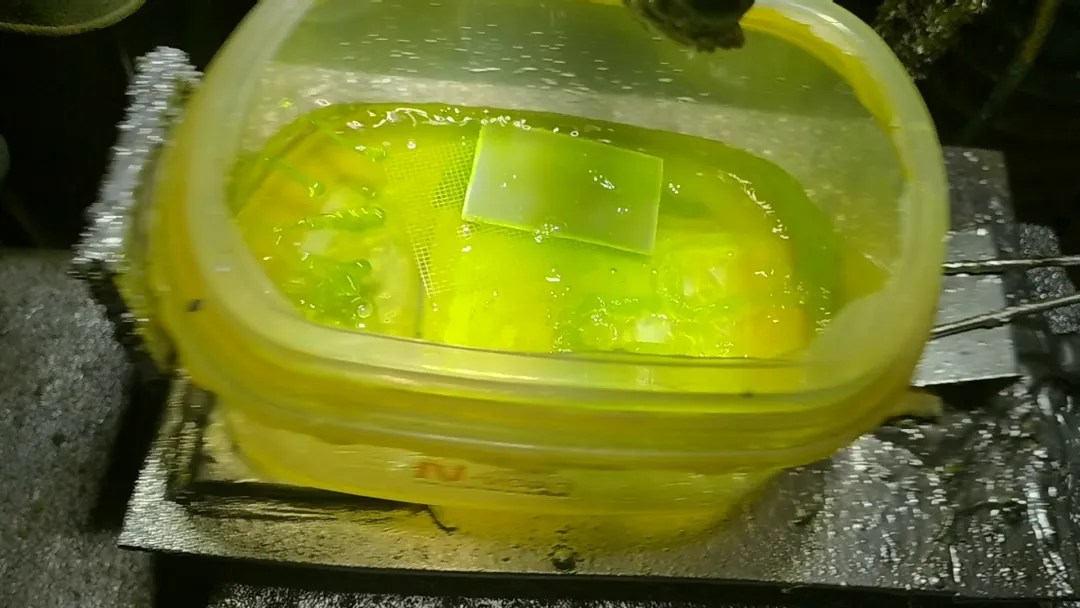
Figure 2 | Etching test with the glass fiber mesh supporting the PCB
Observations Without the Mesh
In the second run, no mesh was used. The board was placed directly into the etching solution and appeared to float near the surface. Without a spacer to support it, the underside of the board had less consistent contact with actively circulating etchant.
Although the process completed, the perceived etch rate was slower compared to the mesh-supported case. In addition, the edges of the board seemed to etch faster than the center. After the reaction, the solution was poured off and the board was rinsed with water.
Comparing final outcomes, the etched pattern quality looked broadly similar, but the path to reach that result differed. After cleaning the toner using an adhesive remover spray, the copper traces were exposed and visually inspected.
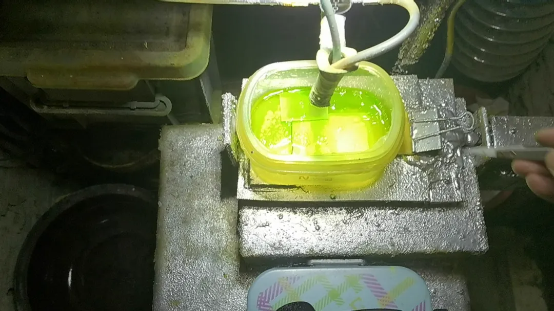
Figure 3 | Etching test without a support mesh under the PCB
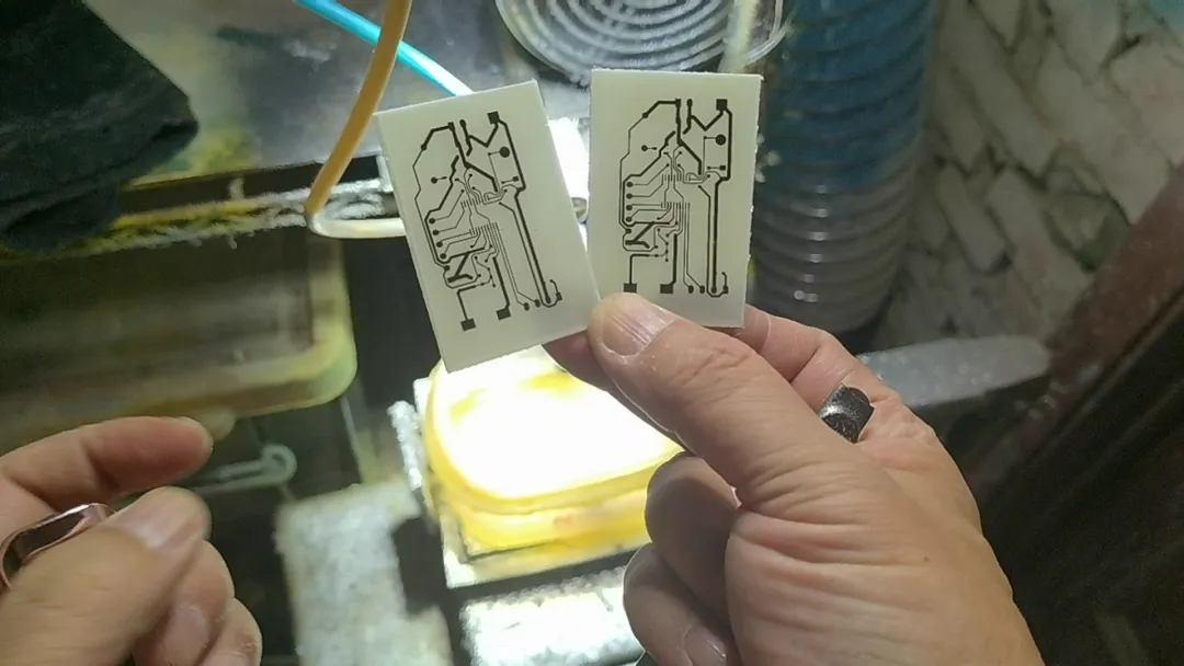
Figure 4 | Copper traces revealed after removing toner following the etch
Why a Mesh Improves Speed and Uniformity
PCB etching is a diffusion- and reaction-limited process. The local rate at which copper dissolves depends on how quickly fresh oxidizing species reach the copper surface and how efficiently reaction byproducts are removed. Several mass-transfer effects explain why a glass fiber mesh spacer can help:
1. Reduced Boundary Layer Thickness
When a flat board rests directly on the bottom of the tank, the liquid boundary layer at the copper/solution interface tends to be thicker in regions with low flow. A thick boundary layer slows diffusion of oxidizers to the copper and slows removal of copper salts from the surface. Elevating the board on a mesh allows solution to move under and around the entire panel, thinning the boundary layer and improving mass transport, particularly in the center where flow is otherwise weakest.
2. More Uniform Flow Under the Board
The mesh creates many small supports that distribute the board’s weight while leaving most of the underside open to flow. Even gentle thermal convection or slight agitation becomes more effective because the mesh provides multiple channels for circulation under the panel. This reduces center-to-edge variations and mitigates the common edge-etching acceleration observed when flow is better at the periphery than the center.
3. Consistent Chemical Access on Both Sides of the Copper Surface
When a board floats on the solution, the underside may have poor contact with fresh etchant, especially if trapped bubbles or surface tension pockets form. The mesh breaks up these pockets and provides stable spacing that encourages continuous wetting and replenishment of reactive species across the underside. This contributes to faster, more uniform copper removal.
4. Enhanced Removal of Reaction Byproducts
As copper dissolves, the etchant locally accumulates copper salts and becomes less reactive. Flow under the board helps carry away these byproducts and replace them with fresh solution. The quick transition to a green color observed in the experiment is consistent with copper chloride formation. Ensuring circulation prevents local depletion or saturation zones from developing under the board.
Explaining the Edge Effect Without a Mesh
In the mesh-free run, the board floated and showed faster etching around the edges compared to the center. This is consistent with an edge effect common in quiescent baths:
- Fresh etchant can access the outer perimeter more easily than the interior, especially without agitation.
- Natural convection near the edges is more effective due to larger exposed surface area and shorter diffusion paths.
- The center region is more prone to stagnant layers, leading to slower etch progress.
The result is a nonuniform etch rate, with edges clearing earlier. While final results may appear similar after a longer time, the process can be less predictable and more prone to undercutting variations and inconsistent line widths, especially for fine features.
Practical Guidance for Using a Mesh in Small-Scale Etching
Mesh Material and Compatibility
- Glass fiber meshes are generally chemically inert in common copper etchants and remain dimensionally stable at typical process temperatures. They also resist compression, maintaining a consistent gap.
- Avoid metal meshes, which can corrode or contaminate the solution.
- Inspect the mesh for sharp fibers that could scratch resist; pre-rinse and deburr if necessary.
Mesh Geometry and Support
- Select a mesh with a moderate pitch to provide stable support without excessively blocking flow. The goal is to maximize open area while preventing the board from sagging or rocking.
- Ensure the board is evenly supported across its area to avoid local tilt that could reintroduce center-to-edge gradients.
Bath Management and Agitation
- Even light agitation significantly improves uniformity. Rocking the tank, using a gentle air bubbler, or periodically moving the board can help.
- Control temperature within a safe and consistent range. Reaction rates increase with temperature, but excessively high temperatures can increase undercut and degrade resist.
- Monitor the solution’s activity. The rapid color change to green indicates copper dissolution and a shift in the etchant’s composition; periodic refresh or regeneration may be needed to maintain rate and uniformity.
Board Preparation and Handling
- Ensure the resist adheres well and that the copper surface is clean before etching. Uneven wetting can cause patchy etches that no mesh can fully overcome.
- Position the board so that trapped air bubbles can escape; slight tilting can help bubbles slide off.
- After etching, rinse promptly and thoroughly to stop the reaction and avoid staining or residues.
Safety Notes
- Peroxide and hydrochloric acid mixtures are reactive and can emit irritating gases. Use in a well-ventilated area, wear appropriate personal protective equipment, and follow safe handling practices for oxidizers and acids.
- Neutralize or dispose of spent solutions responsibly according to local regulations.
Limitations and Trade-offs
While a mesh improves flow and generally accelerates and equalizes etching, consider the following:
- Contact points between the mesh and board can create very small local flow shadows. In practice, these are usually negligible compared to the gains in overall uniformity.
- If the board is not evenly supported, tilting can reintroduce gradients. Check for flat seating on the mesh.
- For very fine-line work, uniformity depends on the entire process chain, including resist quality, etchant chemistry, temperature, and controlled agitation. The mesh is one part of a broader control strategy.
Conclusion
Placing a glass fiber mesh under a PCB during etching elevates the board and enables more effective solution flow underneath. In practice, this can increase etch speed and improve uniformity across the panel, especially mitigating the common edge-faster-than-center effect observed in still baths. In the tests described here, the mesh-supported process ran more smoothly and appeared faster, while the mesh-free run exhibited slower progress and a noticeable edge advantage. Although the final etched results looked similar after cleaning, the mesh provided a more controlled path to reach that outcome.
For small-scale PCB fabrication, a simple glass fiber mesh is a low-cost, chemically compatible tool to enhance etching consistency. Combined with modest agitation and sound bath management, it helps achieve more predictable line widths and cleaner results without major equipment.