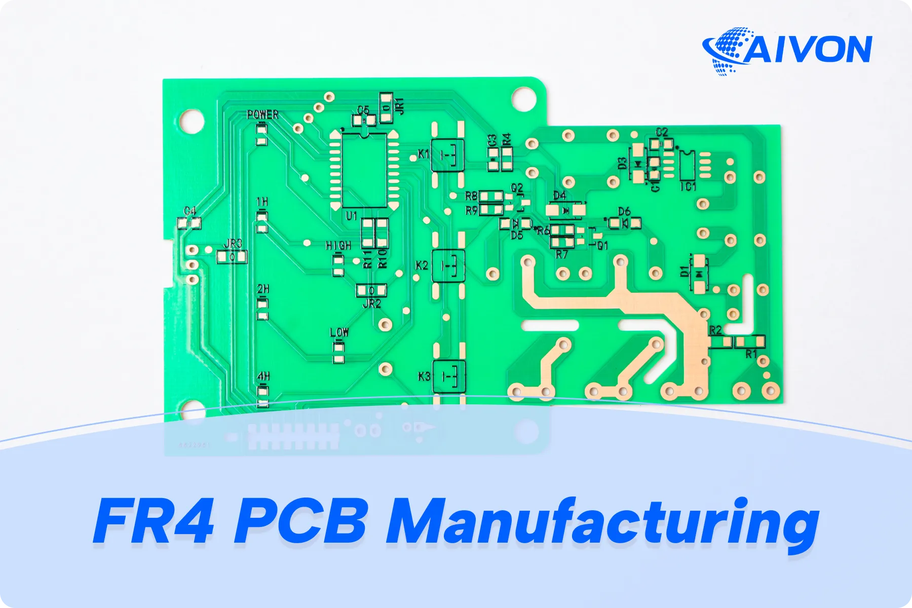
FR4 is not a single laminate. It is a family of glass-reinforced epoxy materials used to manufacture most rigid PCBs. During production, FR4 CCL and prepreg are processed through inner-layer imaging, lamination, drilling, plating, solder mask, surface finishing, and electrical testing. The important point is that FR4 alone does not define Tg, Td, CTE, dielectric properties, or thermal reliability.
This guide explains both how FR4 laminate is manufactured and how finished FR4 PCBs are fabricated, with practical guidance on material selection, reliability, and manufacturing specifications.
What FR4 Materials Actually Are?
FR-4 is a NEMA grade name: Flame Retardant, class 4. The usual flammability target on finished boards is UL 94 V-0. That rating says the coupon extinguishes under a defined flame test. It says nothing about whether the resin will survive two 260 °C reflow peaks without delaminating.
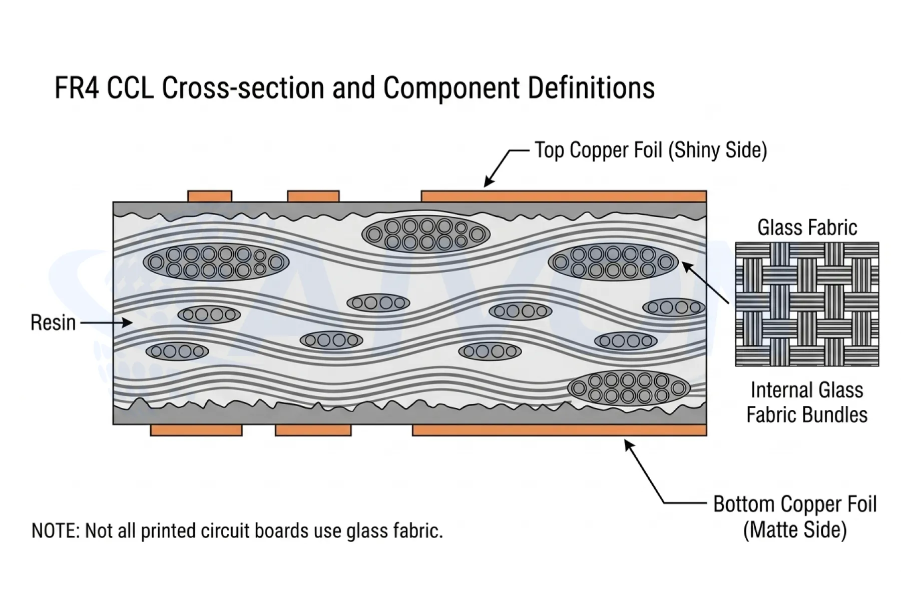
Construction is consistent across the family: woven E-glass fabric, a brominated or halogen-free epoxy resin system, and electrodeposited copper foil. The product that arrives at a PCB shop is not one sheet. Core is fully cured copper-clad laminate used for inner layers and simple 1 to 2 layer boards. Prepreg is partially cured resin on glass; resin flow and gel time determine fill, thickness, and void risk during multilayer press.
One label covers many products because the chemistry and construction knobs are independent:
|
Design Factor |
Typical Options |
Key Impact |
|---|---|---|
|
Resin Functionality |
Difunctional, tetrafunctional, multifunctional epoxies |
Determines crosslink density, Tg, and chemical resistance. |
|
Filler System |
Inorganic fillers |
Reduces Z-CTE and increases Td, but can increase drill wear and narrow the desmear process window. |
|
Glass Style |
106, 1080, 2116, 7628 |
Influences resin content, finished dielectric thickness, Dk, and the glass-weave effect on impedance. |
|
Copper Treatment |
STD, RTF, VLP, HVLP foils |
Affects peel strength, etch factor, and insertion loss. |
FR4 Materials: CCL, Prepreg, and Glass Styles
CCL (copper-clad laminate) is fully cured core. Inner-layer cores are imaged, etched, and oxide-treated before layup. Thin cores and 1–2 layer boards use CCL as the finished dielectric. Thickness tolerance on core is a first-order impedance input; a 0.1 mm core with ±10% thickness scatter already consumes a large fraction of a 10% impedance budget.
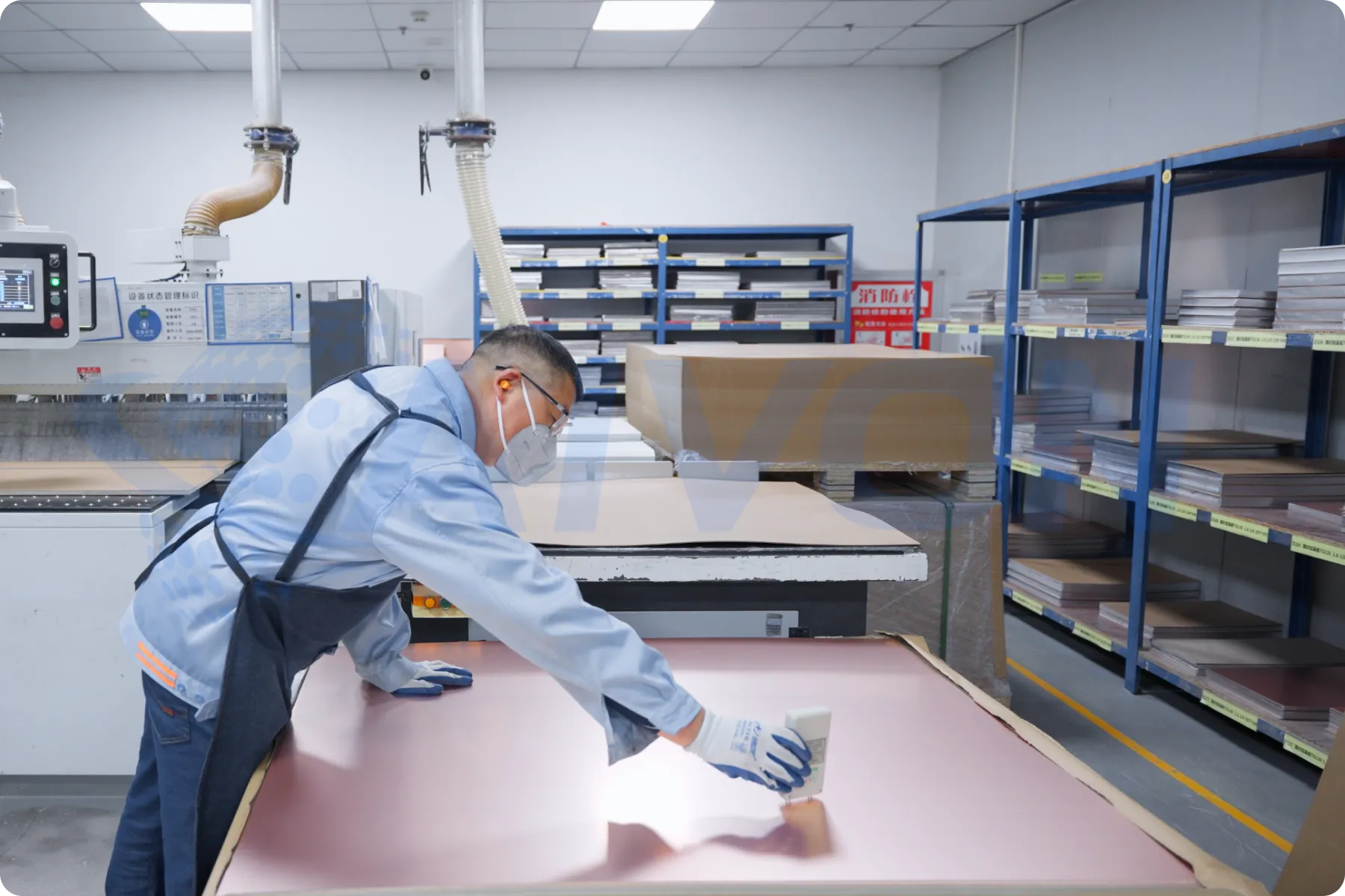
Prepreg is B-stage resin on glass. During press it melts, flows into etched copper topography, and gels. Resin content, volatile content, and gel time are the three incoming parameters that decide whether the stack fills without starvation or squeeze-out. High-resin styles, such as 106, 1080, fill fine features and drop Dk. Glass-rich styles like 7628 add stiffness and raise Dk. Mixing styles without a stackup calculation is how "1.6 mm FR4" boards from two CMs land at different impedances.
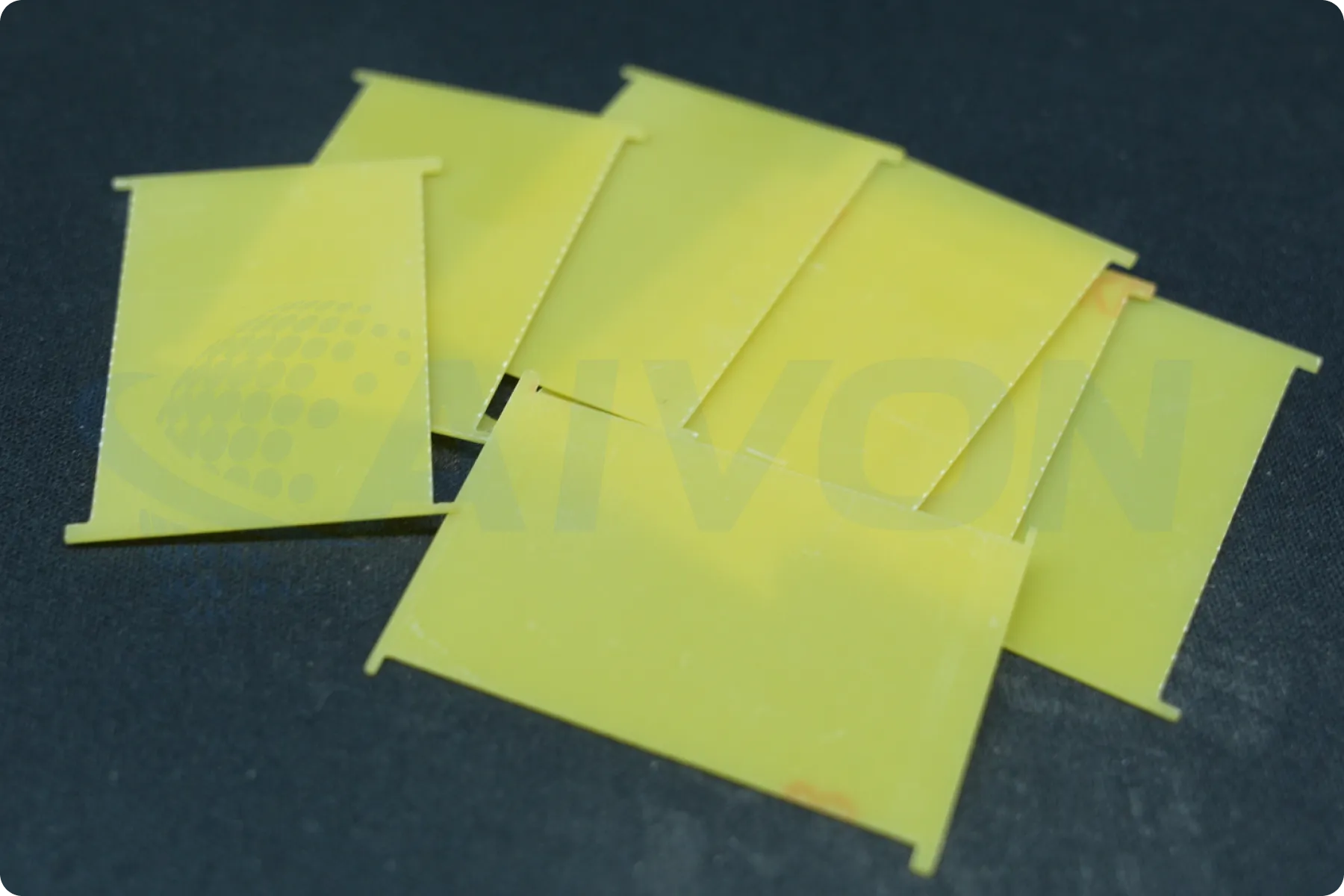
Unclad FR4 sheet is the same resin family without foil. Procurement follows IPC-4101/21 more often than /24. It is not a PCB core substitute. Using unclad sheet as a last-minute inner dielectric is a process control failure, not a cost save.
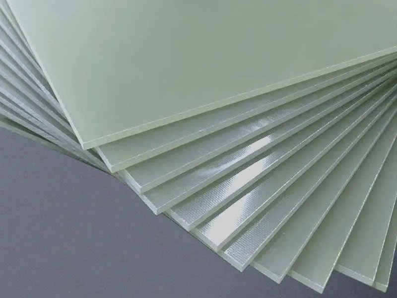
Finished dielectric thickness is not the nominal prepreg thickness on the datasheet. After press, resin has flowed into the copper pattern. High copper remaining on inner layers reduces compressed dielectric thickness and raises local Dk. Designers who ignore residual copper when calculating stackup will see impedance coupons fail even when the laminate lot is in spec.
FR4 Grades and Material Properties
Shop-floor grades are thermal bins, not marketing names:
|
FR-4 Type |
Typical Tg |
Typical Examples |
Main Characteristics |
|---|---|---|---|
|
Standard Tg FR-4 |
~130–140 °C |
Shengyi S1141, Nanya NP-140 |
General-purpose FR-4 for standard PCB applications. |
|
Mid-Tg FR-4 |
~150–160 °C |
Nanya NP-155F, Shengyi S1000H |
Higher thermal stability than standard Tg FR-4; suitable for more demanding applications. |
|
High-Tg FR-4 |
~170–180 °C |
Shengyi S1000-2 / S1000-2M, ITEQ IT-180A, Isola 370HR |
Provides higher thermal resistance and improved reliability for high-temperature processing and applications. |
|
Halogen-Free FR-4 |
Typically mid- to high-Tg |
Br <900 ppm; Cl <900 ppm; Br + Cl <1500 ppm per IEC 61249-2-21 |
Uses halogen-free chemistry to meet environmental and material requirements; Tg varies by material system. |
|
Enhanced-Electrical/Low-Loss FR-4 |
Material-dependent |
Glass-epoxy systems with improved electrical performance |
Reduces dielectric loss compared with commodity FR-4 when Df begins to limit high-speed channel length; not equivalent to Rogers high-frequency laminates. |
IPC Standards for FR-4
FR-4 work is specified against a small set of IPC documents. They do not pick the brand for you. They set the floor the laminate and the finished board have to meet.
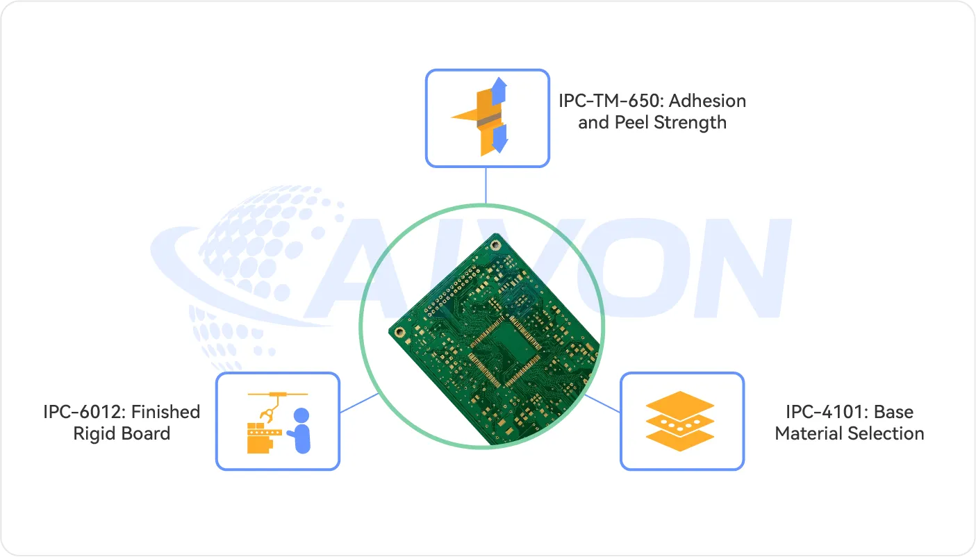
IPC-4101 covers the base material. Slash sheets such as /24, /42, and /99 define what FR4 must deliver for Tg, Td, construction, and halogen status. Put the slash sheet on the drawing if you do not want a generic core.
IPC-6012 covers the finished rigid board: copper in the hole, plating class, bow and twist, and acceptance for Class 2 or Class 3. Material grade and board class are separate calls.
IPC-TM-650 is the test methods book behind both. Tg, Td, T-288, peel, moisture, and many reliability screens are run to these procedures. A CoC number without a method is hard to compare.
FR4 Material Parameters That Affect PCB Manufacturing
Values below are typical production ranges, not guaranteed limits.
|
Parameter |
Standard Tg (TG130) |
Mid-Tg (TG150) |
High-Tg (TG170) |
Why fabrication cares |
|---|---|---|---|---|
|
Typical Tg |
130–140 °C |
150–170 °C |
170 °C+ |
Softening point during reflow and press |
|
Td |
~300–310 °C |
~320–330 °C |
~340–350 °C |
Irreversible resin breakdown |
|
Moisture absorption |
0.12–0.18% |
0.10–0.15% |
0.08–0.12% |
Bake, CAF, popcorning |
|
Dk |
4.2–4.6 |
4.2–4.6 |
4.1–4.5 |
Impedance and stackup |
|
Df |
0.015–0.025 |
0.015–0.025 |
0.010–0.020 |
Loss at higher bit rates |
|
Typical layer range |
1–6 |
4–12 |
8–20+ |
Sequential lamination survival |
|
Relative laminate cost |
1.0× |
1.10–1.20× |
1.20–1.40× |
BOM vs scrap risk |
|
Example products |
Shengyi S1141, Nanya NP-140 |
NP-155F, S1000H |
S1000-2 / S1000-2M, ITEQ IT-180A, Isola 370HR |
Named spec on fab drawing |
Secondary parameters that still belong on a serious RFQ:
● Peel strength after thermal stress (IPC-TM-650 2.4.8)
● CTI for high-voltage tracking (IEC 60112)
● Thermal conductivity, typically about 0.3 W/m·K on unfilled FR4. Filled high-Tg systems can read higher. FR4 is not a heat spreader.
● Flexural modulus and dimensional stability after press
● CAF resistance rating and test coupon geometry
How FR4 Laminate and Prepreg Are Manufactured
Two factories sit in the supply chain. The laminator makes CCL and prepreg. The PCB fabricator turns those sheets into a circuit. Defects that look like fab problems often started as resin content scatter, undercure, or foil treatment variation at the laminator.
Laminate process step by step:
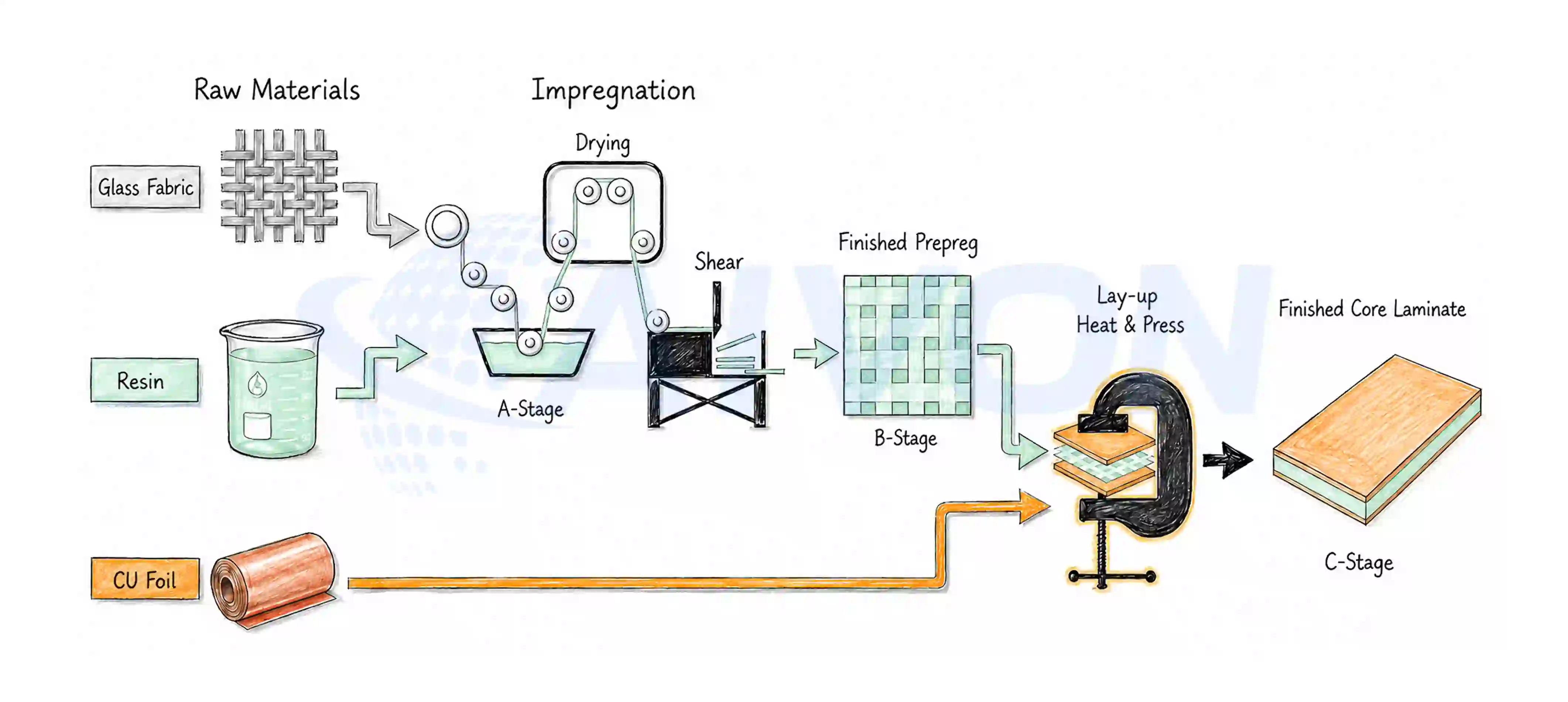
1. Resin formulation. Epoxy, hardener, flame retardant, fillers, solvents, and flow modifiers are mixed to a target viscosity and solids content. Phenolic-cured systems generally deliver higher Td and better lead-free endurance than older dicy systems at the same Tg bin.
2. Glass cloth treating / impregnation. Woven E-glass is dipped or coated so resin wets every filament. Incomplete wet-out becomes a CAF path later.
3. B-stage drying. Solvent is driven off under controlled heat. The output is prepreg with specified resin content, volatile, and gel time.
4. Book build. Copper foil, prepreg plies, and release films are stacked to the ordered core thickness and copper weight.
5. Press lamination. Typical window is about 170–200 °C, 2–4 MPa, vacuum assist, 60–120 min depending on resin. High-Tg and filled systems sit at the hot, long end of that range.
6. Cool, trim, inspect. Thickness, copper adhesion, appearance, and often Tg coupons are checked before slitting.
7. Slit to panel size. UL marking and lot traceability are applied. That lot code is what the fabricator should transcribe onto the traveler and the CoC.
Process variables that later show up as PCB defects: uneven resin content produces thickness and Dk scatter; poor foil treatment produces peel failures after thermal stress; undercure produces delamination in the first or second reflow, not at incoming AOI.
FR4 PCB Fabrication Process: Step by Step
Most FR4 production is the same job repeated at different complexity. A 1–4 layer board is one lamination cycle: cores and prepreg go to press, then the panel is drilled, plated, patterned, masked, and finished. That is the everyday flow in a rigid PCB shop. Layer count is what changes the work. Six to eight layers still use one press, but registration, copper balance, and bake control start to matter more. Eight to sixteen layers and HDI add sequential lamination, buried or blind vias, and often laser drilling. The factory line does not change names. The board simply goes through press, drill, and plate more than once, and the laminate grade has to survive those extra heat cycles.
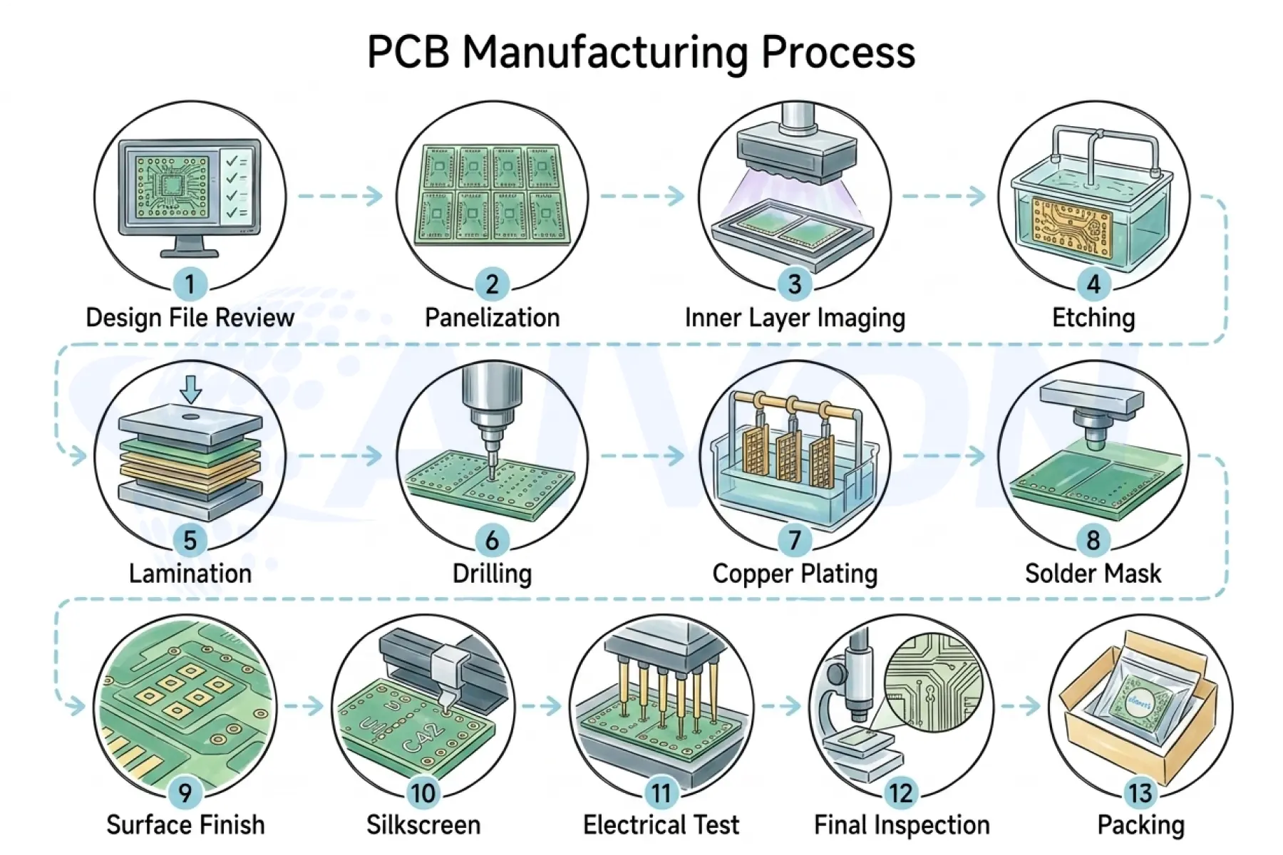
1. Incoming laminate verification and stackup release
2. Inner-layer clean, image, etch, strip, AOI
3. Oxide or oxide-alternative treatment
4. Layup and multilayer press
5. Drill, desmear, PTH plate
6. Outer-layer image and etch
7. Solder mask and legend
8. Surface finish
9. Route, electrical test, impedance coupons
10. Final inspect and moisture-barrier pack
FR4 Manufacturing Considerations and Common Defects
FR4 production is stable when the grade matches the thermal stack and the layout is symmetric enough to press flat. Most defects are not random shop errors. They come from a drawing that only says FR4, a copper imbalance the press cannot hide, or a finish that does not match the footprint. Three issues show up most often:
PCB Warpage and Twist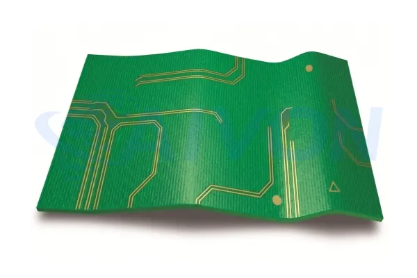
Residual copper on top and bottom differs too much, or the stack is not mirrored. The panel bows in press and again in reflow. Balance the pours, or allow fill in blank areas away from pads and holes. Changing Tg or surface finish will not flatten an unbalanced board.
Delamination and Via Strain
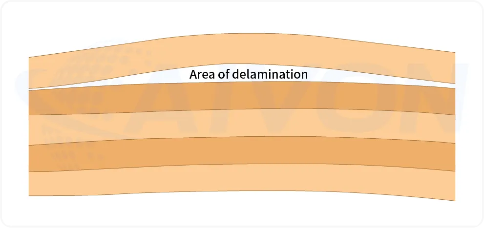
Standard-Tg FR4 spends a long time above Tg in a lead-free profile. On six or more layers, multiple reflow, or HDI, the usual result is measling, pad cratering, or barrel cracks. Specify mid- or high-Tg with a Td that fits the profile. Bake wet lots before press and assembly.
Drilling, Resin Smear, and Hole-Wall Quality
FR4 drills cleanly when the recipe matches the resin. High-Tg and filled systems are harder and more abrasive. Leave standard-Tg feeds on those lots and the bit smears resin over the inner-layer junctions. Poor desmear leaves a film that plating cannot bond to. Over-desmear attacks the glass-resin interface and opens a CAF path.
Plating and Via Reliability
Via life is copper thickness and adhesion in the barrel, not the finish on the pad. Thin plating, voids at the inner-layer junction, or smear left under the copper will pass a simple continuity test and fail after thermal cycle. Call the IPC-6012 class and the minimum copper in the hole. High aspect ratio and sequential lamination need the higher-Tg, lower-CTE laminate as well. Class 3 notes with Class 2 plating defaults are a common way this defect is designed in.
Impedance and Dimensional Variation
Dk and finished dielectric thickness move with glass style, resin content, and how much copper remains after etch. A drawing that only says "FR4, 50 Ω" leaves those knobs to the shop. Press squeeze-out, core tolerance, and an unbalanced pour then show up as coupon scatter and bow. Give a construction-specific stackup, a Dk/Df target at the frequency you care about, and copper-balance rules. Treat impedance and warp as stackup problems first, not as drill or solder-mask problems.
Surface Finish Selection on FR4 Boards
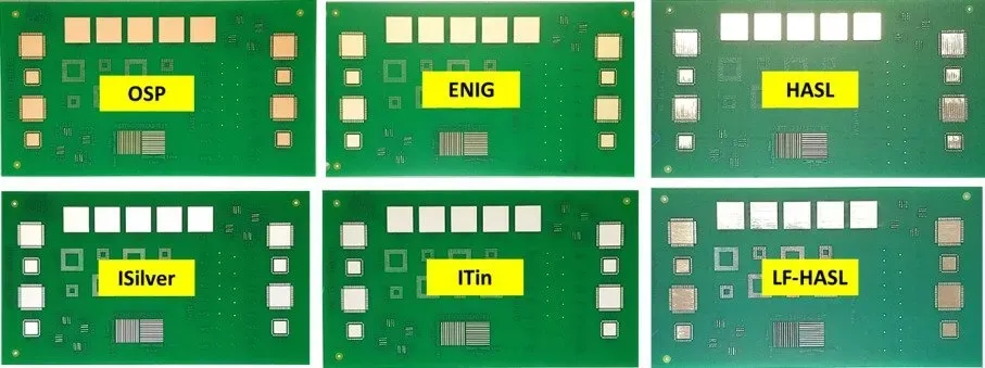
Surface finish is the last coating on exposed copper pads and holes. Bare copper oxidizes in air and becomes hard to solder, so the fabricator covers it before the board leaves the shop. On FR4 work the common choices are lead-free HASL, OSP, ENIG, immersion silver, and ENEPIG. Immersion tin is used less often on multilayer lead-free boards. The finish decides pad flatness, shelf life, how many reflow cycles the board can take, and whether a fine-pitch BGA will sit flat. It does not change the laminate. A wrong Tg still cracks vias after ENIG is applied.
The table below compares those five production finishes. Use it to match pitch, assembly profile, and inventory time, not to repair a material grade that was specified too low.
Surface Finish Comparison Table
|
Finish |
Flatness |
Shelf life |
Reflow cycles |
Fine-pitch/BGA |
Cost |
Watch-outs |
|---|---|---|---|---|---|---|
|
LF HASL |
Poor–fair |
6–12 months |
Good |
Weak below ~0.5 mm pitch |
Low |
Uneven pads, not for fine BGA |
|
OSP |
Excellent |
3–6 months |
Limited |
Good if assembled soon |
Lowest |
Short window, handling, bake |
|
ENIG |
Excellent |
12+ months |
Good |
Excellent |
Mid |
Black pad if Ni/Au out of control |
|
Immersion Ag |
Excellent |
6–12 months |
Good |
Good |
Low–mid |
Tarnish, sulfur, handling |
|
ENEPIG |
Excellent |
12–24 months |
Excellent |
Excellent + wire bond |
High |
Cost; over-specified on simple boards |
FR4 Compliance and Material Certification
On an FR4 board, compliance usually means the metals and organics in the laminate, copper, soldermask, and surface finish. It does not mean the board will survive reflow, and it does not replace a Tg or Td callout. Buyers still mix three different asks: substance limits (RoHS, REACH SVHC), halogen-free OEM rules, and factory papers such as UL or a Certificate of Compliance.
For standard FR4 PCB production, RoHS-capable materials and finishes are commonly available, but the exact compliance package depends on the laminate, finish, and customer requirements.
Halogen-free FR4 is a separate OEM request. It is not automatic on a standard RoHS board. UL 94 V-0 and a UL yellow card attach to a specific laminate construction, not to the letters FR4. If the end customer needs halogen-free, a named UL construction, or a later SVHC list than the published reports, say so before the order is placed.
For a normal FR4 job, pick OSP, lead-free HASL, or ENIG on the quote. Those three finishes are the ones covered by the published SGS RoHS and REACH reports. No extra form is required for standard substance compliance.(https://www.aivon.com/faq/orders/sgs-rohs-reach-compliance-for-aivon-pcb-products/)
How to Select the Right FR4 Material
The conversion question is simple: which FR4 should this board use? Rank criteria by risk, not by the order of datasheet pages.
1. Assembly chemistry and reflow count: leaded vs lead-free; single vs double-sided vs rework
2. Layer count and sequential lamination/HDI
3. Max continuous operating temperature and thermal cycling
4. Reliability class: IPC Class 2 vs 3, automotive, industrial, medical
5. Electrical: impedance tolerance, bit rate, and when to leave commodity FR4 for enhanced-electrical or mid-loss
6. Environment/OEM halogen and substance rules
7. Volume, lead time, and approved-vendor list
Application-Based Quick Picks
|
Application |
Typical pick |
|---|---|
|
Consumer IoT, LED, 2–4 layer |
Standard or mid-Tg + HASL or OSP |
|
Industrial control, 4–8 layer lead-free |
Mid- or high-Tg + ENIG |
|
Automotive ECU / power |
High-Tg, CAF-capable, IATF supply chain + ENIG or ENEPIG |
|
Server / multilayer backplane |
High-Tg low-CTE, Td ≥340 °C |
|
Medical / regulated consumer |
High-Tg or HF high-Tg + full RoHS/REACH pack |
|
High-voltage |
CTI-rated FR4 and creepage rules, not a Tg-only choice |
AIVON FR4 Manufacturing Experience
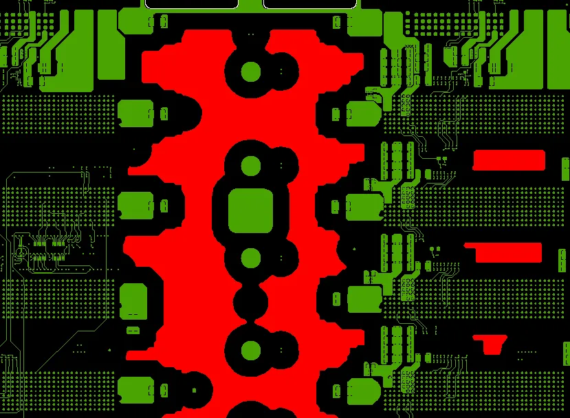
AIVON builds routine stackups from stock material: FR4, TG150, halogenated resin. That grade is the everyday mid-Tg choice for lead-free 2–8 layer work. It does not correct a one-sided copper pour. When residual copper on TL and BL differs too much, bow and twist are hard to hold to the shop limit of ≤0.75%. CAM then adds balance copper in the blank areas on the sparse side, 6 mm away from traces, pads, and drilled holes. On the markup, that copper is shown in red.
Why is FR4 particularly sensitive to copper distribution imbalances?
FR4 consists of fiberglass cloth and epoxy resin with copper cladding. During manufacturing, the board undergoes lamination, drilling and plating, and lead-free reflow soldering. During each heating cycle, the resin softens as it passes the glass transition temperature; the difference in thermal expansion between the copper and the dielectric material pulls the board toward the side with less copper.
This effect is more pronounced in boards with fewer layers or thinner profiles. For 2-layer or 4-layer boards, the top and bottom layers face each other directly without internal planes to provide structural support. Even with 8 or more layers, if the copper distribution between inner and outer layers is asymmetrical, warping will still exceed limits. High-Tg materials only shorten the window of time during which the resin remains soft; they cannot compensate for a disparity in copper surface area.
Therefore, material selection addresses the risk of delamination during reflow, while copper pouring addresses the risk of board bending. High-Tg or ENIG will not flatten that panel. Symmetry will. Keep top and bottom residual copper close in the layout, or allow the 6 mm clearance pour on the empty face and on the breakaway tab. If a face must stay empty for assembly, say so on the note so the red pour is not added by default.
Conclusion
The most important lesson in FR4 selection is simple: FR4 is a starting material category, not a complete engineering specification.
A manufacturable PCB specification should identify the laminate grade or approved family, Tg and Td, relevant CTE behavior, IPC-4101 classification, electrical requirements, copper construction, surface finish, and compliance requirements.
The right material decision also depends on the fabrication process. Lamination, drilling, desmear, plating, solder mask, and surface finish all respond to material characteristics. A material change should therefore trigger a manufacturing review rather than being treated as a purchasing-only substitution.
FAQs
Q1: What is the difference between FR4 TG130, TG150, and TG170?
A1: TG130 is a standard FR4 grade with a glass transition temperature around 130–140 °C by DSC, while TG150 provides a higher thermal margin and is commonly used for lead-free multilayer boards. TG170 combines a higher Tg with properties such as higher decomposition temperature (Td), lower Z-axis thermal expansion, and longer T-288 resistance. When selecting FR4, compare actual Tg, Td, CTE, and T-288 data rather than relying only on the material grade name.
Q2: Is standard FR4 compatible with lead-free (RoHS) soldering?
A2: Standard FR4 can sometimes withstand a single moderate lead-free soldering profile, particularly on simple two-layer boards. Multilayer boards, repeated reflow, and rework require greater thermal reliability, so Td and T-288 should be evaluated in addition to Tg. RoHS-compliant solder alloy does not by itself improve the thermal performance of the laminate.
Q3: Does halogen-free FR4 perform the same as standard FR4?
A3: Halogen-free FR4 can achieve the same UL 94 V-0 flame rating as conventional FR4, but other material and processing characteristics may differ. Moisture behavior, processing window, drilling and desmear performance, and cost can vary by material system. When halogen-free construction is required, material-specific bake and humidity controls should be established.
Q4: Which surface finish is best on FR4 for BGA and multiple reflow?
A4: ENIG and ENEPIG are commonly selected for BGA applications because they provide a relatively flat surface and good solderability through multiple assembly cycles. OSP can also be suitable when inventory turnover and storage conditions are tightly controlled. Lead-free HASL may be less suitable for fine-pitch BGA because its surface height variation is generally greater than that of planar finishes.
Q5: Why did my FR4 board warp or delaminate after assembly?
A5: Common causes include insufficient laminate thermal performance for the assembly profile, excessive moisture, an asymmetric stack-up, incomplete press curing, and unbalanced copper distribution. These factors can create thermal stress and dimensional changes during reflow. Solder paste itself is usually not the first factor to investigate when diagnosing FR4 warpage or delamination.