Most sheet metal bend relief design mistakes show up the same way on the shop floor. The flange looks fine in CAD. Then the press brake hits it and the material at the bend ends either cracks, tears, or buckles. The part is scrap or needs secondary grinding.
Bend relief is not optional decoration. It is a deliberate cut that gives the material room to stretch and compress without concentrating stress at the edge of the bend line.
What Bend Relief Actually Does During Forming
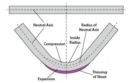
When a flange is bent, the material on the inside of the radius compresses. The material on the outside stretches. At the free ends of the bend, those two forces meet the unbent sheet. Without a relief, the corner tries to stay connected to both the flange and the web at the same time. Stress spikes. Crack starts.
The relief interrupts that continuous edge. It lets the stretched outer fiber pull free and the compressed inner fiber fold without fighting the adjacent material.

Thickness, bend radius, and material ductility all change how much room is needed. Soft aluminum forgives more than cold-rolled steel. Hardened stainless forgives almost nothing.
Why Engineers Skip or Undersize the Relief
Three patterns keep showing up in design reviews.
First, the model simply has no relief. The designer treated the bend as a pure geometric fold. CAD tools will happily create a sharp corner. The tool shop will not.
Second, the relief exists but is too small. Width is set to half the material thickness or less. Depth stops at the theoretical bend line instead of extending past the outer radius. On the brake the material still bridges the gap and tears.
Third, the relief is placed in the wrong location. It sits inside the bend zone or starts after the bend line has already begun. The stress concentration just moves a few millimeters and the crack still appears.
These choices are rarely intentional. They usually come from copying a previous part that happened to work with a more forgiving material, or from defaulting to the minimum feature size the CAD library offers.
What Happens When the Relief Is Wrong
No relief or undersized relief produces three predictable failures.
Cracking. The outer fiber exceeds its elongation limit at the free edge. A sharp crack runs from the corner along the bend line. On thin stock the crack may stop after a few millimeters. On thicker plate it can run the full length of the flange.
Tearing. The material tries to stretch around the punch radius while still attached to the web. The corner rips free, leaving a jagged edge that needs secondary cleanup. The flange length also becomes inconsistent because material is pulled away from the intended geometry.
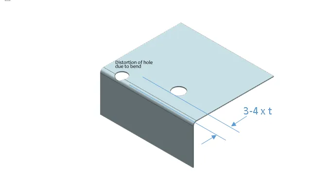
Local deformation. Even if the edge does not crack, the unrelieved corner can push the flange out of square or create a bulge in the web. The part may pass visual inspection but fail when it is assembled against a flat mating surface.

These defects are expensive. Once the part is formed, the only recovery options are grinding, welding, or scrap. None of them restore the original material properties or dimensional accuracy.
Practical Relief Dimensions That Survive the Brake
A workable starting rule for most mild steel and aluminum is simple.
Width of the relief: at least equal to material thickness. Prefer 1.5× thickness when the bend radius is large or the material is harder.
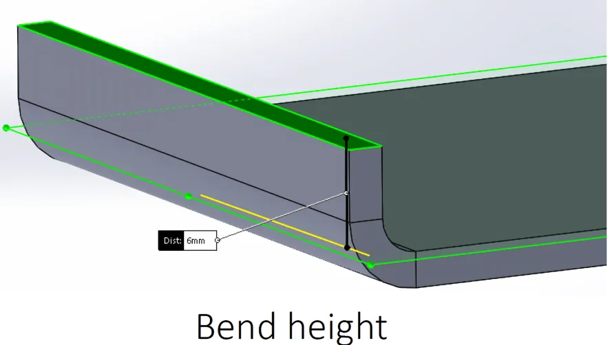
Depth of the relief: bend radius plus material thickness, measured from the theoretical bend line outward. This places the end of the relief past the outer fiber so the stretched material is free.
Shape: rectangular is preferred for most press-brake work. Round or filleted ends reduce stress concentration further but require more careful programming of the laser or punch. Avoid V-notches unless the geometry forces them; they reintroduce a sharp stress riser.
Location: the relief must begin exactly at the intersection of the bend line and the free edge. Offset it and the stress concentration simply relocates.
For stainless and high-strength alloys the numbers grow. Width often needs to reach 2× thickness. Depth may need an extra half-thickness of clearance. When the flange is short relative to thickness, the relief can consume most of the available length; in that case the designer has to decide whether the flange is even formable.
Design Checks That Catch the Mistakes Early
Before the file leaves the design station, three quick checks eliminate most sheet metal bend relief design mistakes.
Confirm every bend that ends at a free edge has a relief. Internal bends that run into a continuous wall usually do not need one; free ends always do.
Measure the relief against actual material thickness and bend radius, not against the nominal CAD thickness. Sheet tolerance and actual formed radius both affect the required clearance.
Look at the flat pattern. The relief should appear as a clean rectangular slot or notch that does not leave thin webs of material that the laser or punch will struggle to hold.
If the part uses progressive dies or hard tooling, the relief geometry also has to clear the punch and die clearances. A relief that works on a press brake can still cause tool interference in a progressive die.
One more practical note. When the same part is made from different gauges, the relief must be scaled with thickness. A relief sized for 1.5 mm stock will be too small on 3 mm stock and will tear the thicker material.

Engineering Takeaway
Bend relief exists to protect the free edge of a formed flange. Missing it, undersizing it, or placing it incorrectly concentrates forming stress exactly where the material is least able to absorb it. The result is cracking, tearing, or local distortion that appears only after the part is already in the press.
Treat the relief as a functional feature, not an afterthought. Size it to material thickness and bend radius, align it to the bend line, and verify it on the flat pattern. Those three steps eliminate the majority of sheet metal bend relief design mistakes before any metal is cut.