In production we flag any hole that sits closer than 1.5–2 times material thickness from the part edge during the first DFM pass. That single check on sheet metal hole to edge distance decides whether the blank will punch or laser cleanly without edge tear-out or bulge. Most shops default to a minimum web of 2×T for punched parts and accept 1.5×T only when the process is laser-only and the material is mild. Anything tighter forces a tooling or process change before the job is released to the floor.
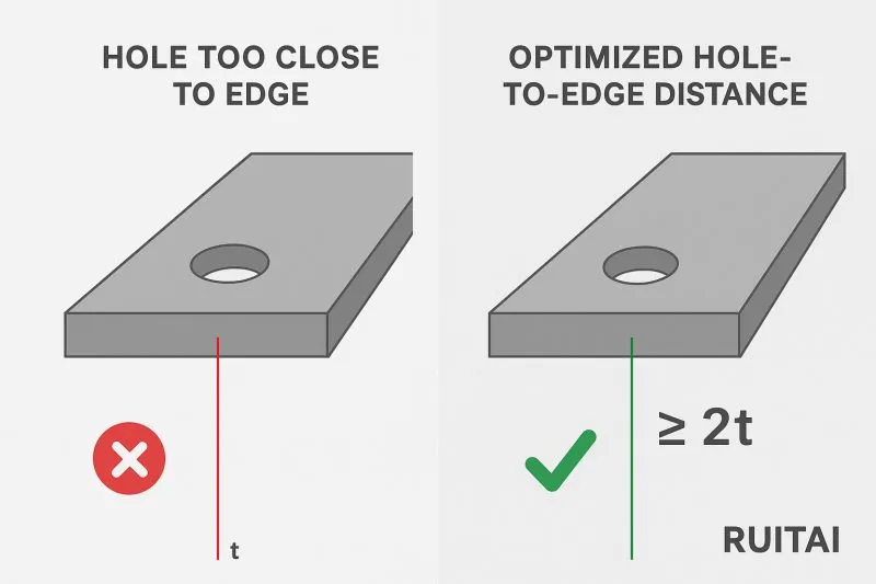
Hole-to-edge distance is the remaining solid material between the edge of a cut feature and the outer contour of the part. It is not the same as center-to-edge dimension. When the web becomes too narrow the punch or laser leaves the remaining strip under high stress. In punching the material is sheared and displaced; a thin web cannot resist that displacement and either cracks or bulges outward. In laser cutting the heat-affected zone and the residual cutting force can still pull the thin edge out of flatness. The relationship to hole diameter also matters: shops prefer the hole diameter itself to be at least equal to thickness, otherwise the punch tip is overloaded and the edge quality around the hole degrades even if the web looks adequate on paper.
Why thin webs show up as edge tear-out and bulge on the press
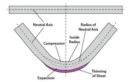
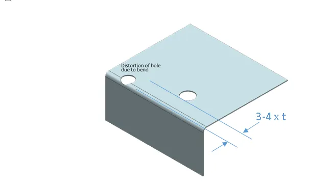
The problem is forced by the physics of the cutting process itself. Punching creates a shear zone that expands slightly beyond the punch diameter. When the remaining web is less than roughly 1.5–2×T that shear zone reaches the free edge and the material simply opens or displaces. Laser cutting avoids the mechanical shear but still concentrates thermal stress; a narrow web cools unevenly and can warp or leave a raised ridge. Harder alloys and stainless exaggerate both effects because they have less ductility to absorb the local strain. Once the part also carries a bend nearby, the same thin web becomes the path of least resistance for the forming stresses, turning a round hole into an oval or tearing the edge completely.
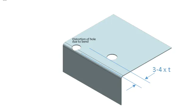
If the distance is left uncontrolled the shop sees concrete losses. Edge tear-out produces scrap that cannot be salvaged. Bulged edges fail go/no-go gauges or cause fit-up problems at assembly. Holes that sit too close to a bend line ovalize during forming, so clearance holes no longer accept the intended fastener and threaded holes lose their form. Inspection time rises because every borderline part must be checked with a radius gauge or optical comparator. In high-volume runs the extra secondary operations—drilling after forming, edge grinding, or 100 % visual sort—add cost and delay shipment. Customers eventually see the same defects after vibration or load and the return conversation starts.
How the shop actually enforces and recovers the distance
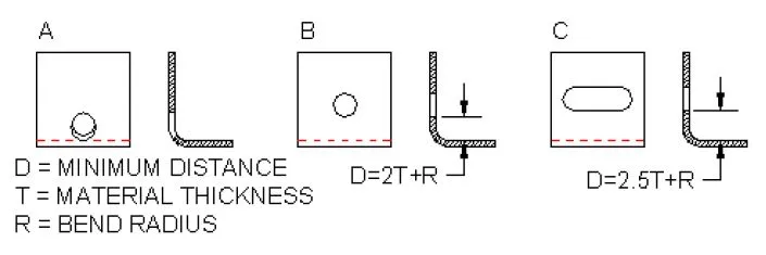
CAM engineers measure the web on every hole during nesting review. For punched parts the default rule is a minimum 2×T from hole edge to part edge; for laser-only jobs 1.5×T is usually accepted provided the material is not stainless or high-strength steel. When the design also includes bends the more restrictive rule applies: the edge of the hole must stay at least 2×T (preferably 2.5×T + inside bend radius) away from the bend tangent line so the hole remains outside the plastic deformation zone. If the drawing violates the rule the first response is to move the hole or enlarge the flange. When the feature cannot move, the process is switched to laser if the original plan was punching, or the hole is left blank and drilled after forming. Special soft punches or slower stroke speeds are sometimes used for marginal webs, but they raise cycle time and tool wear.
Hole diameter is checked at the same time. A hole smaller than material thickness is rarely punched cleanly; the shop either opens it to ≥T or moves it to laser/drill. For structural or load-bearing holes the web is further checked against the classic 1.5× diameter center-to-edge rule so tear-out strength remains acceptable. Nesting programs are set to flag any feature that falls inside the minimum zone; the operator then either accepts a process change or returns the file for redesign. On the floor the first-article inspection always includes a quick web measurement with calipers or a profile projector before the batch is released.
A practical design checklist used on the CAM desk is short and consistent: confirm every hole diameter ≥T; keep hole-edge-to-part-edge ≥1.5×T (laser) or ≥2×T (punch); keep hole-edge-to-bend-tangent ≥2×T or 2T+R; orient critical holes away from the grain direction when possible; and note any secondary drilling that will be required after forming. Following these sheet metal hole to edge distance rules keeps the blank inside the normal process window and avoids the majority of edge and forming defects.
When the shop will accept a tighter web and what is traded
Exceptions are limited. Soft aluminum or copper under 1.5 mm thickness can sometimes run at 1×T web on laser with acceptable edge quality. Prototype or low-volume cosmetic parts may be accepted with a 1.2×T web if the customer signs off on minor bulge risk and 100 % inspection is added. When a hole must sit closer to a bend for functional reasons the shop may laser the hole oversized and ream after forming, or add a small relief slot so the deformation does not reach the hole. In all these cases the quotation carries a note on elevated scrap risk and extra process steps. Once the part moves to regular production the preference returns to the standard 1.5–2×T web so the job stays inside normal cycle times and yield targets.
Keeping the web inside these limits is the simplest way to protect both edge quality and form accuracy. The rules are not arbitrary; they match the actual behavior of the material under the punch or laser and under the press brake.