In the fab shop we treat bend radius as a tooling and material decision before it becomes a design feature. When a drawing lands on the CAM desk the first check is whether the called-out inside radius can be produced with standard press-brake punches and the actual material grade on the floor. For most mild-steel jobs in air bending we target an inside radius equal to or slightly above material thickness. Anything tighter forces us to confirm ductility, grain direction, and whether the punch tip radius exists in the tool library. That is the practical starting point for sheet metal bend radius design guidelines on every production order.

Inside radius is not an independent number. It is locked to thickness and to how the material behaves under the punch. In air bending the formed inside radius settles at roughly 15–20 % of the V-die opening for mild steel; the punch tip mainly sets the minimum possible radius rather than the final value. When the drawing demands a radius smaller than thickness, the outer fibers stretch beyond the elongation limit of the alloy. Soft aluminum and annealed copper tolerate 0.5–1×T. Cold-rolled mild steel usually accepts 0.8–1×T up to 6 mm thickness. Stainless and harder aluminum tempers (6061-T6, full-hard 301) need 1.5–3×T or more before the outside surface stays intact. Once thickness exceeds 6–8 mm the multiple climbs further because the volume of material that must flow increases and spring-back becomes harder to predict.
Why the outside of the bend starts to crack when radius drops below the material limit
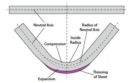
Cracking appears first on the tension side. The outer surface is forced to elongate while the inner surface compresses. If the inside radius is too tight relative to thickness and the alloy's ductility, the outer fibers exceed the material's uniform elongation and microscopic tears form. Those tears open into visible cracks after the part is removed from the brake. Grain direction makes the problem worse: bending parallel to the rolling direction reduces the effective elongation by 20–40 % compared with bending across the grain. Harder tempers and higher-strength stainless simply have less plastic strain capacity, so the same radius that works on 5052-H32 aluminum will split 6061-T6 or 304 stainless of the same thickness. In production we see this most often on parts that arrived with a radius drawn as a sharp corner or as 0.5×T "to save space."

If the radius stays uncontrolled the consequences show up quickly on the floor. Scrap rate climbs because cracked parts are usually not salvageable by re-bending. Visual inspection and dye-penetrant checks catch the worst cases, but micro-cracks that later open under vibration or thermal cycling still escape. Assembly fit suffers when the actual outside radius grows larger than the drawing predicted because of uncontrolled spring-back. Tooling takes extra wear: forcing a sharp radius on thick stock loads the punch tip heavily and shortens tool life. In high-volume runs the extra setups required for special punches or intermediate annealing steps add hours to the schedule and push delivery dates out. Customer returns for "unexpected cracking after installation" become a recurring conversation once the part leaves the shop.
How the shop actually selects and holds the radius in production
Process engineers start with the material certificate and the available punch and die inventory. Standard air-bending practice for mild steel up to 3 mm is an inside radius of 0.8–1×T using a punch tip close to that value and a V-die whose opening is 6–8×T. For stainless the same thickness we move to 1.5–2×T and a wider die to reduce strain rate. Aluminum 5052 stays near 1×T; 6061-T6 is forced to 2–3×T or the part is annealed first. When the drawing calls for a radius that does not match any standard punch we either machine a special tip (cost and lead-time penalty) or negotiate a change to the next larger standard radius. Grain orientation is checked on the nesting layout so that critical bends run across the grain whenever possible. K-factor is set according to the actual radius-to-thickness ratio (typically 0.33–0.42 for air bends under 1×T, rising toward 0.45–0.50 as the radius grows) so that the flat-pattern calculation stays accurate and the final flange lengths land inside tolerance.
On the brake the operator verifies the formed radius with a radius gauge after the first piece. If the measured value drifts because of material batch variation or tool wear, the program is adjusted by changing punch penetration or by swapping to a slightly larger tip. Bottoming or coining is used only when the design absolutely requires a sharper radius and the material can tolerate the higher tonnage; even then we keep the radius no smaller than 0.5×T for soft alloys and document the higher residual stress. For multi-bend parts we keep the same radius on every flange so that one punch setup covers the entire sequence and cycle time stays predictable.

Recommended minimum inside radii that keep production stable across common gauges are straightforward. Up to 6 mm thickness: aluminum 1×T, mild steel 0.8×T, stainless 2×T. From 6 mm to 12 mm the multiples rise to 1.5×T, 1.2×T and 2.5×T respectively. Above 12 mm the values climb again because the material volume and the risk of surface rupture both increase. These numbers are the ones that appear on most shop DFM checklists and that match the tooling most fabricators keep on the rack.
When the shop will accept a tighter radius and what is traded away
Exceptions exist for thin soft alloys, short-run prototypes, and parts that can be annealed between stages. Soft aluminum or copper under 1.5 mm can often be formed at 0.5×T with a polished punch and slow stroke speed; the yield drop is small enough that the cost is acceptable. When the design cannot change and the material is hard, we may accept a 1×T stainless radius provided the bend is oriented across the grain, the edges are deburred before forming, and 100 % visual inspection is added. The trade-off is higher scrap allowance, longer cycle time, and the possibility of residual stress that later affects dimensional stability or fatigue life. In those cases the quotation notes the elevated risk and the customer is asked to confirm the functional need for the tighter radius. Once the part moves into regular production the preference always returns to a radius that matches standard tooling and the material's natural forming limit.
Following these sheet metal bend radius design guidelines keeps the part inside the process window the brake operators and tooling already know. The result is fewer cracked flanges, predictable flat patterns, and delivery dates that do not slip because of unexpected forming problems.