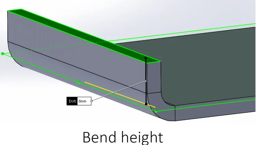
In production we treat the minimum flange height as 4 times material thickness plus the inside bend radius for standard air-bending on press brakes. Programming and tooling setup reject anything shorter unless the job is switched to a folding machine or special narrow-die tooling. That is the practical sheet metal flange design guidelines rule we apply every day before the part ever hits the brake.
Most shops measure the flange from the outside of the bend to the free edge. For 1.5 mm mild steel that means a finished height no less than about 7–8 mm. Soft aluminum can go a little tighter; stainless and high-strength steels usually need the full 4× or more. If the drawing shows less, the CAM engineer flags it during the first tool-path review.
Why short flanges keep slipping off the die during air bending
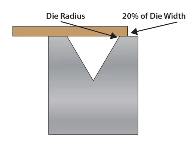
The limitation is mechanical. Air-bending dies are selected so the V-opening is roughly 6–8 times material thickness. The punch has to push the sheet into that opening while the two shoulders of the die support the material on either side of the bend line. A flange that is shorter than about half the V-width simply falls into the die or tilts under the punch force. Once that happens the bend angle becomes uncontrolled and the edge deforms.
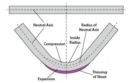
Material spring-back makes the problem worse. Thicker or higher-strength sheet needs more over-bend, which increases the force on the unsupported edge. Grain direction also plays a role; bending parallel to the rolling direction reduces ductility and raises the chance that a marginal flange will crack at the outer radius.
Panel nesting and blank size add another constraint. When several parts share a sheet, short flanges often sit too close to laser-cut edges or to neighboring features, leaving no room for the back-gauge fingers or the die clearance. That is why the same short-flange call-out that looks fine on a single-part drawing becomes a production stop once the job is nested.
What happens on the floor when the flange is left undersized
The most common result is an incomplete or open angle. The operator tries to force the bend, the flange buckles, and the part is either scrapped or sent back for hand correction. In high-volume runs that scrap rate climbs fast—sometimes 15–20 % of the batch—because the first few pieces look acceptable until cumulative spring-back and tool wear push the process over the edge.
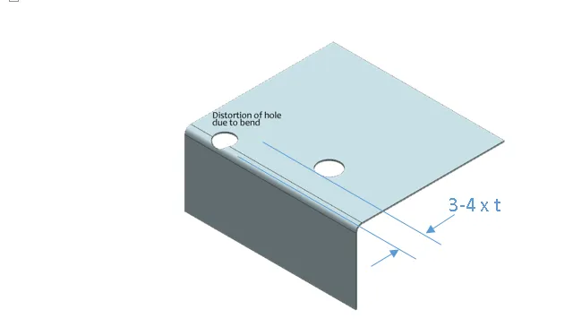
Holes or slots placed near the short flange distort as well. The material stretches unevenly, so the hole becomes oval and no longer matches the mating fastener. Assembly then fails at the customer's line, generating a non-conformance report that lands back on the fab shop.
Tooling damage is quieter but expensive. Repeated attempts to form an undersized flange dig into the die shoulders or chip the punch tip. Once that happens the whole tool set has to be pulled for re-grinding, stopping the machine for half a shift or more. Delivery dates slip and overtime appears on the next week's schedule.
How the shop actually brings short flanges under control
First action is always a design flag. The programming team returns the drawing with a note that the flange must be lengthened to 4× thickness + inside radius, or the bend must be re-oriented so a longer edge can be formed first. Most customers accept the change once they see the scrap cost.
When the design cannot change, we switch tooling. Narrower V-dies (down to 4–5× thickness) allow shorter flanges, but they raise the required tonnage and increase the risk of die marks. Soft aluminum and thin mild steel can usually tolerate the higher pressure; stainless often cannot without surface cracking.
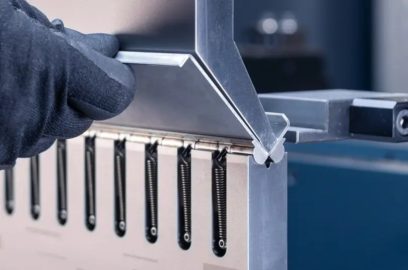
Folding machines become the next option. A folder clamps the sheet and folds the flange with a beam rather than pushing it into a V-die, so the minimum length drops to roughly 2× thickness + radius. The trade-off is slower cycle time and limited capacity for long parts. We reserve folders for prototype or low-volume jobs that cannot wait for a design revision.
For production runs we sometimes add a temporary process tab. A small rectangular extension is left on the flange during laser cutting, the bend is formed using the tab for support, then the tab is sheared off. That keeps the die contact points intact without changing the final part geometry. The extra shear operation costs a few seconds per piece but saves the entire batch from scrap.
Bend sequence is also adjusted. Short flanges are formed last so the rest of the part can still rest solidly on the die. If two short flanges sit opposite each other, the second bend often requires a custom gooseneck punch or a staged setup. Those extra setups are quoted and scheduled up front so the customer is not surprised by the lead-time increase.
When the factory can relax the 4× rule
Soft annealed aluminum under 1 mm thick can often run at 3× thickness if the bend radius is kept equal to or larger than the thickness and the grain is oriented correctly. Prototype quantities of fewer than ten pieces can be formed by hand or on a folding machine without formal tooling approval. Parts that will be welded into a larger assembly sometimes accept a slightly open angle because the weld will pull the flange into position later.
Strengthening features change the calculation as well. A short flange that carries a continuous bead or a small emboss gains enough stiffness to survive the bend without buckling, so the height rule can be eased by about 0.5× thickness. The same is true for flanges that end in a hem or a return flange; the extra material at the free edge acts as a natural support during forming.
Assembly function also influences the decision. If the flange only provides a mounting surface for a self-clinching nut or a simple screw clearance, a small amount of edge deformation is often tolerated provided the hole location remains within ±0.2 mm. Functional sealing or sliding surfaces, on the other hand, never get that latitude.
In every case the shop still measures the finished flange after the first article. If the height or angle falls outside the agreed tolerance, the job stops until either the design or the process is corrected. That single checkpoint keeps the short-flange problem from traveling downstream into assembly or shipping.