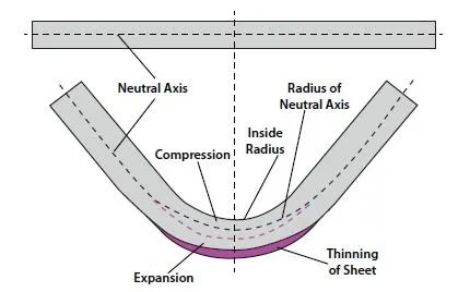
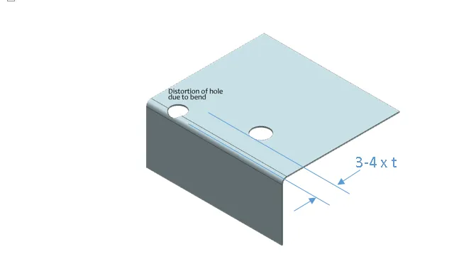
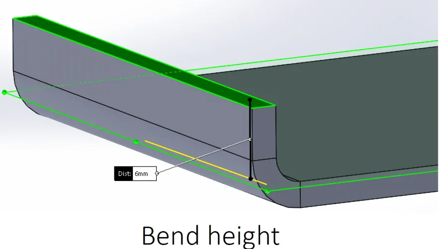
In sheet metal fabrication, the debate over k factor vs bend allowance sheet metal is not academic. It shows up every time a flat pattern is generated, a press-brake program is written, or a first-article part fails to meet print. One approach relies on a theoretical ratio of the neutral axis; the other relies on an absolute arc length measured or calculated for a specific bend. Choosing the wrong one under the wrong production conditions costs material, machine time, and yield.
K-Factor or Bend Allowance: Which Parameter Actually Controls Flat-Pattern Accuracy?
From a fabrication standpoint, K-factor is the better default when the same material, thickness range, and tooling are used across many jobs and the CAM system must remain consistent. Bend allowance becomes the better choice when the shop already has measured data from the exact press brake, punch, and die combination that will run the part. Most shops start with a standard K-factor, then lock in a measured bend allowance once the process is proven. The decision is driven by whether the priority is speed of programming or final dimensional reliability.
Side-by-Side Comparison of the Two Parameters
| Dimension | K-Factor | Bend Allowance |
|---|---|---|
| Definition | Ratio locating the neutral axis inside the material thickness | Absolute length of the curved portion of the bend |
| Typical value range | 0.30–0.50 for most air-bent mild steel | Calculated or measured in mm or inches for each bend |
| Manufacturing complexity | Low – single number entered in CAM | Higher – requires either formula or empirical measurement |
| Sensitivity to thickness | Indirect – changes with thickness only through neutral-axis shift | Direct – scales linearly with thickness and radius |
| Tooling dependence | Moderate – assumes standard air-bend conditions | High – changes with punch radius, die opening, and tonnage |
| Lead time impact | Faster programming for new parts | Slower until measured data is captured |
| Yield risk | Higher on first-article if default K is wrong | Lower once the measured value is locked |
| Typical applications | Prototype, multi-job shops, standard material libraries | High-volume production, tight-tolerance parts, exotic alloys |
Decision Matrix: Which Parameter Wins Under Different Shop Priorities
| If your priority is... | Better Choice | Why |
|---|---|---|
| Fastest CAM programming for new parts | K-Factor | One number covers the entire material library; no per-bend measurement needed |
| First-article dimensional accuracy | Bend Allowance | Measured arc length removes the uncertainty of the neutral-axis assumption |
| Consistent results across multiple press brakes | K-Factor | Tooling differences are absorbed into a single ratio that can be adjusted globally |
| High-volume production with tight tolerances | Bend Allowance | Once measured, the value is locked and yield stays high for the entire run |
| Working with soft or work-hardening alloys | Bend Allowance | Neutral-axis location shifts more than standard K tables predict |
| Quick quoting and nesting | K-Factor | Flat-pattern length can be generated without waiting for a sample bend |
How the Two Parameters Are Mathematically Linked
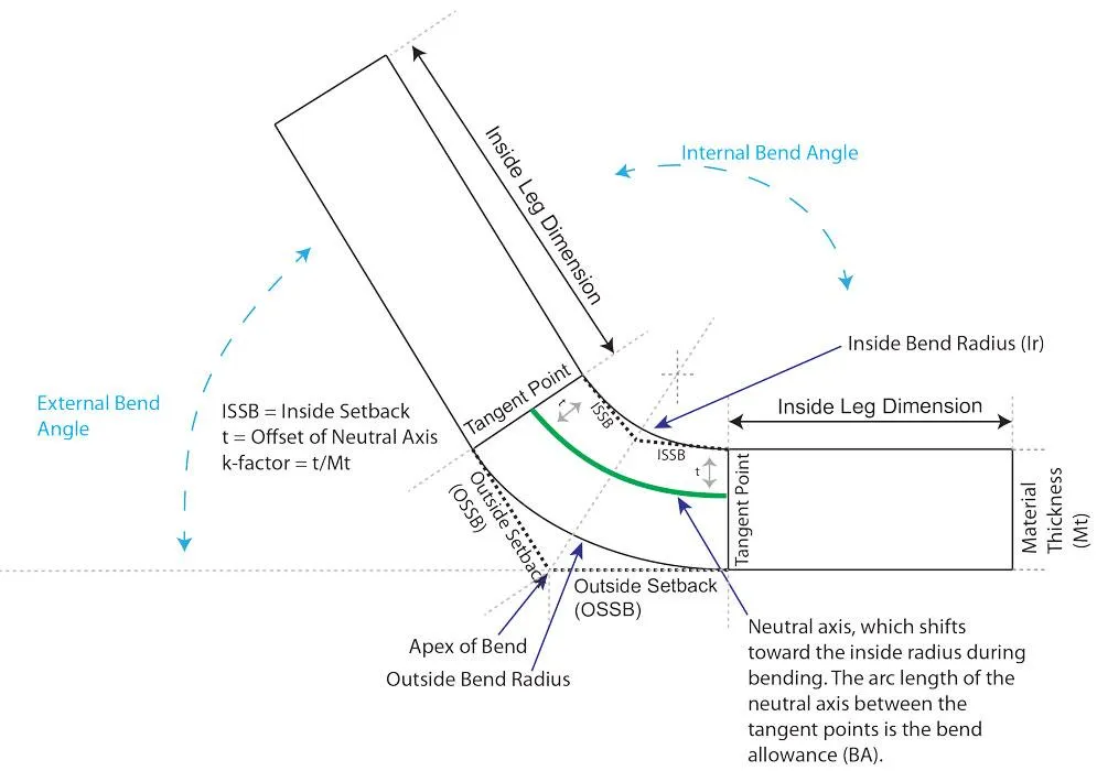
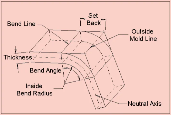
K-factor and bend allowance are not independent. The bend allowance is calculated from the K-factor:
BA = (π/180) × Bend Angle × (Inside Radius + K × Thickness)
Once BA is known, the developed length of any flange is simply the two straight legs plus the bend allowance. In production, the practical difference is whether the programmer enters the K value and lets the software compute BA, or enters a measured BA directly and bypasses the theoretical formula. Most modern CAM systems accept either input; the shop decides which one is more trustworthy for the job at hand.
Where Material Thickness Starts to Change the Decision
For thin sheet (0.5–1.5 mm), the neutral axis stays close to the geometric center and a default K of 0.33–0.40 is usually safe. As thickness increases beyond 3 mm, the neutral axis moves outward more than the standard tables predict, especially with larger die openings. In those cases the calculated bend allowance based on a fixed K begins to under- or over-estimate the actual arc length. Shops that run heavy plate routinely switch to measured bend allowance after the first setup bend because the error compounds across multiple bends on the same part.
The reverse is also true: when thickness is held constant and only the bend radius changes, K-factor remains more stable. Changing the punch radius by a few millimeters alters the measured bend allowance significantly, while the same K value can often still be used with acceptable accuracy.
Air Bending, Bottoming, and Coining Change the Preferred Parameter
Air bending is the most common process and the one for which published K-factor tables are written. In air bending the material contacts only the punch tip and the die shoulders; the neutral-axis location is relatively predictable. K-factor works well here.
Bottoming and coining force the material into full contact with the die. The neutral axis shifts, spring-back drops, and the actual arc length can differ from the air-bend formula by several tenths of a millimeter. Under these conditions most fabrication houses abandon the theoretical K and measure the bend allowance on a sample. The measured value is then locked into the program for the production run.
From a process-stability viewpoint, the more the bending method departs from free air bending, the stronger the case for using a measured bend allowance rather than a calculated K-factor.
What Appears on the Engineering Drawing and What the Shop Actually Uses
Engineering drawings rarely list a K-factor. They show finished outside dimensions, bend radii, and sometimes a note such as "bend allowance per shop standard." The fabricator is expected to develop the flat pattern correctly. During CAM preparation the programmer must decide whether to pull a default K from the material library or to use a previously measured bend allowance for that exact tooling combination.
When the drawing calls for a tight tolerance on overall length after multiple bends, the safer manufacturing choice is to cut a sample, measure the actual developed length, back-calculate the true bend allowance, and then run production from that value. Relying on a generic K-factor under those conditions is the most common source of first-article rejection.
How a Sheet-Metal Shop Evaluates the Two Options in Daily Production
During DFM review we look at three things: number of bends, tolerance stack-up, and whether the material and tooling already exist in our library. If the part has fewer than four bends and the tolerance is ±0.5 mm or looser, a standard K-factor is accepted without further discussion. If the part has six or more bends or the overall length tolerance is ±0.2 mm, we flag the job for a sample bend and measured bend allowance before releasing the program.
Panel utilization is rarely affected by the choice, but scrap rate is. A systematic 0.3 mm error on every bend quickly consumes the available stock on a tightly nested sheet. That is why high-volume jobs almost always migrate from a theoretical K to a locked bend allowance once the process is proven.
Tooling considerations also matter. When the same die set is used for many different thicknesses, K-factor libraries must be maintained carefully. When a dedicated tool is set up for one thickness only, measuring the bend allowance once and storing it with the tool setup sheet is simpler and more reliable.
Which Parameter Should You Choose for the Next Job?
Choose K-Factor when you:
- Are programming prototypes or low-volume parts
- Work primarily with standard mild steel or aluminum in the 0.8–3 mm range
- Need to generate flat patterns quickly for quoting or nesting
- Run the same material and thickness across many different tools and want one consistent number
- Can accept a first-article adjustment if the theoretical value is slightly off
Choose Bend Allowance when you:
- Are launching a high-volume production run
- Have overall length tolerances tighter than ±0.3 mm after multiple bends
- Are bending thick plate, stainless, or work-hardening alloys
- Use bottoming or coining rather than pure air bending
- Already possess measured data from the exact press-brake setup that will run the job
Neither parameter is universally superior. The correct manufacturing choice is the one that matches the production conditions of the specific job.
Frequently Asked Questions
Q1: Can I convert a measured bend allowance back into a K-factor for my material library?
A1: Yes. Rearrange the BA formula to solve for K. Once calculated, that K can be stored for future jobs that use the same material, thickness, and tooling. Many shops maintain both the measured BA and the derived K.
Q2: Why do published K-factor tables sometimes give different values for the same material?
A2: Tables assume different bend methods (air vs bottom) and different ratios of inside radius to thickness. Always match the table conditions to your actual process; otherwise the calculated bend allowance will be wrong.
Q3: Is it better to use bend deduction or bend allowance in CAM software?
A3: Bend allowance is more intuitive because it is a positive length added to the legs. Bend deduction is simply the difference between the outside setback and the bend allowance. Both produce the same flat pattern if calculated correctly; most modern systems prefer bend allowance.
Q4: How much error is typical if I use a default K of 0.33 on every job?
A4: On thin mild steel with a generous radius the error is often under 0.2 mm per bend. On thick stainless or with a sharp radius the error can exceed 0.5 mm per bend and stack up quickly on multi-bend parts.
Q5: Should the same K-factor be used for both the length and the width directions on a part?
A5: In theory yes, because K is a material and process property. In practice, grain direction and prior rolling can shift the neutral axis slightly. For critical parts, measure bend allowance in both directions if the blank is sheared from coil.
Q6: When does the difference between k factor vs bend allowance sheet metal stop mattering?
A6: Once the process is locked, the part is running in volume, and the measured bend allowance (or the derived K) has been proven on first article, further debate is unnecessary. The shop simply uses the locked value until the tooling or material changes.