In production we handle sheet metal assembly design by locking the joining method to the sheet thickness, load path and service requirement before any hole is punched. Self-clinching PEM inserts and standoffs take priority for PCB mounting structures because they give clean, permanent threads without secondary operations. Screws are reserved for field-serviceable joints only. Welding and solid riveting stay limited to structural frames where vibration or high shear loads rule out threaded fasteners. The rule is simple: choose the joint that can be installed on the press brake or punch line in one hit and still leave the assembly open for board swaps.
Where hole tolerance and material spring-back force the fastener choice
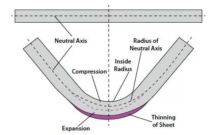
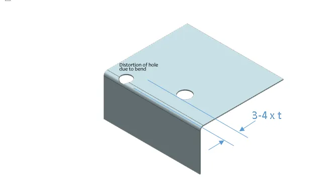
What we typically see on the CAM and tooling side is that every bent flange or embossed feature moves the hole location by 0.1–0.3 mm once the part leaves the press. That shift is enough to turn a floating screw into a hard interference or leave a PEM insert half-seated. Thin aluminum (0.8–1.2 mm) springs more than cold-rolled steel; thicker galvanized sheet can crush under clinch force if the die is not matched. Because the panel is nested and punched before bending, the designer's nominal hole size is already compromised by cumulative tooling wear and material variation. This is why production forces the decision early: either the joint must tolerate that movement (loose screw clearance) or the insert must be installed while the flat blank is still accurate.
Nut columns and standoffs for PCB mounting amplify the problem. A 10 mm or 15 mm tall standoff multiplies any angular error at the base into several tenths of a millimetre at the board surface. If the sheet is not flat after forming, the board sits on three points and the fourth corner lifts, cracking solder joints or stressing connectors. That is pure process geometry, not design preference.
What fails on the line when the joining method is left open
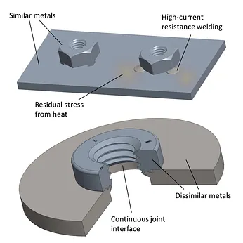
Ignore the constraint and the first symptom is stripped threads during board installation. Operators force the screw, the insert spins, and the panel is scrap. On high-volume lines that shows up as a 3–5 % yield drop before anyone notices the root cause. Welded nuts that sit proud after distortion force extra shimming or grinding; the extra labor adds minutes per unit and still leaves residual stress that can crack the weld under thermal cycling. Solid rivets that cannot be removed turn a simple field PCB swap into a full enclosure replacement, driving warranty cost and customer downtime.
Misaligned standoffs also create immediate assembly stops. The board will not drop into place, the automated screwdriver rejects the joint, and the line stops while a technician tries to persuade the parts to fit. That delay compounds across the shift and usually ends in a late shipment or an expensive hand-rework station.
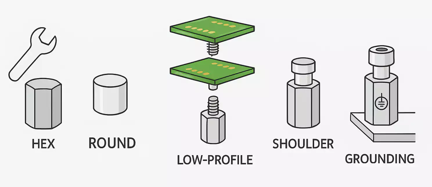
How the shop actually locks the joint and keeps cost down
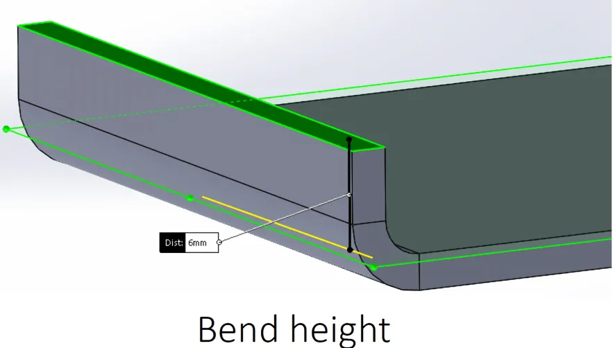
Most factories solve sheet metal assembly design by fixing three parameters at the blanking stage. First, hole diameter for PEM hardware is held to the manufacturer's published tolerance—typically +0.05 / –0.00 mm for steel and a slightly looser window for aluminum—so the clinch bead forms fully without cracking the sheet. Second, standoffs for PCB mounting are installed only on flat, unbent surfaces; any required bend is placed at least 1.5 times the material thickness away from the insert edge. Third, the joining sequence is written into the process sheet: clinch inserts while the blank is flat, form the flanges, then add screws or rivets only where access is still open.
When welding is unavoidable we switch to projection welding of square nuts rather than freehand MIG. The projection gives consistent heat input and keeps the nut face flush within 0.1 mm. Riveting is reserved for permanent structural seams; we use self-piercing rivets where possible so no pre-punched hole is required and the joint can be made after painting. For maintenance-critical panels the rule is clear: every PCB mounting point must be a threaded insert or standoff that can be accessed with a standard screwdriver from one side only. That single decision cuts field service time by more than half and eliminates the need for special tools.
Cost is controlled by reducing the number of unique fastener types on a given panel. One PEM nut size and one standoff height cover 80 % of electronics enclosures we run. Extra hardware types force extra feeder bowls, extra inventory and extra change-over time. We therefore push designers to standardize early; the shop will not open a second clinch station just to accommodate a one-off M4 insert when an M3 already works.
When the factory will accept a less rigid joint
Low-volume or prototype runs can relax the clinch requirement and use ordinary screws with captive washers if the customer accepts longer assembly time. Soft aluminum panels under 0.8 mm sometimes cannot hold a standard PEM; in those cases we allow a floating cage nut or a welded stud, provided the load is low and the board can be removed without stress. High-vibration environments occasionally force a locked weld or solid rivet even on a serviceable panel; the trade-off is documented and the customer is told the board will no longer be field-replaceable. Outside those three cases the production default remains self-clinching hardware for every threaded joint that carries a PCB.