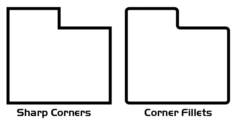
In production we handle sheet metal cutout design guidelines by applying process-specific minimums on hole size, edge distance and slot aspect ratio before the job ever reaches the laser or punch. CAM review flags any opening that falls below 1× material thickness for round holes or 1.5× thickness for slots, then either rejects the feature or forces a process change to water-jet or slower laser settings. Rectangular openings get 0.5–1 mm corner radii added automatically if the designer left sharp corners, because the tooling will tear or the laser will leave a slag bead that has to be deburred later.
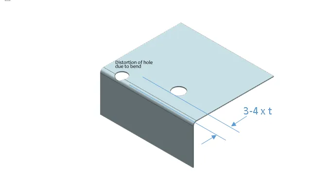
Most factories run the same rule set regardless of whether the part is 0.8 mm aluminum or 2 mm steel: minimum hole diameter equals material thickness for laser, 1.2× thickness for CNC punch. Edge-to-edge distance between any cutout and the outer panel edge or another opening is held at 1.5× thickness minimum; anything tighter produces local distortion when the sheet is nested and the residual stress from cutting is released.
Where the cutting process itself forces the size and spacing rules
The limits appear because laser kerf, punch tool clearance and heat-affected zone all scale with thickness. On a 1.5 mm mild-steel sheet the laser beam leaves a 0.2–0.3 mm kerf; if the designed hole is only 1.2 mm, the remaining web is too narrow to keep dimensional stability after the sheet cools. Punch tooling needs clearance of roughly 10 % of thickness per side, so a 3 mm hole in 2 mm stock already sits at the edge of what the die can strip cleanly. When the nesting program places parts edge-to-edge to maximise yield, any cutout closer than 1.5× thickness to the panel perimeter warps the stripper plate contact area and the whole panel comes off the machine with a slight bow.
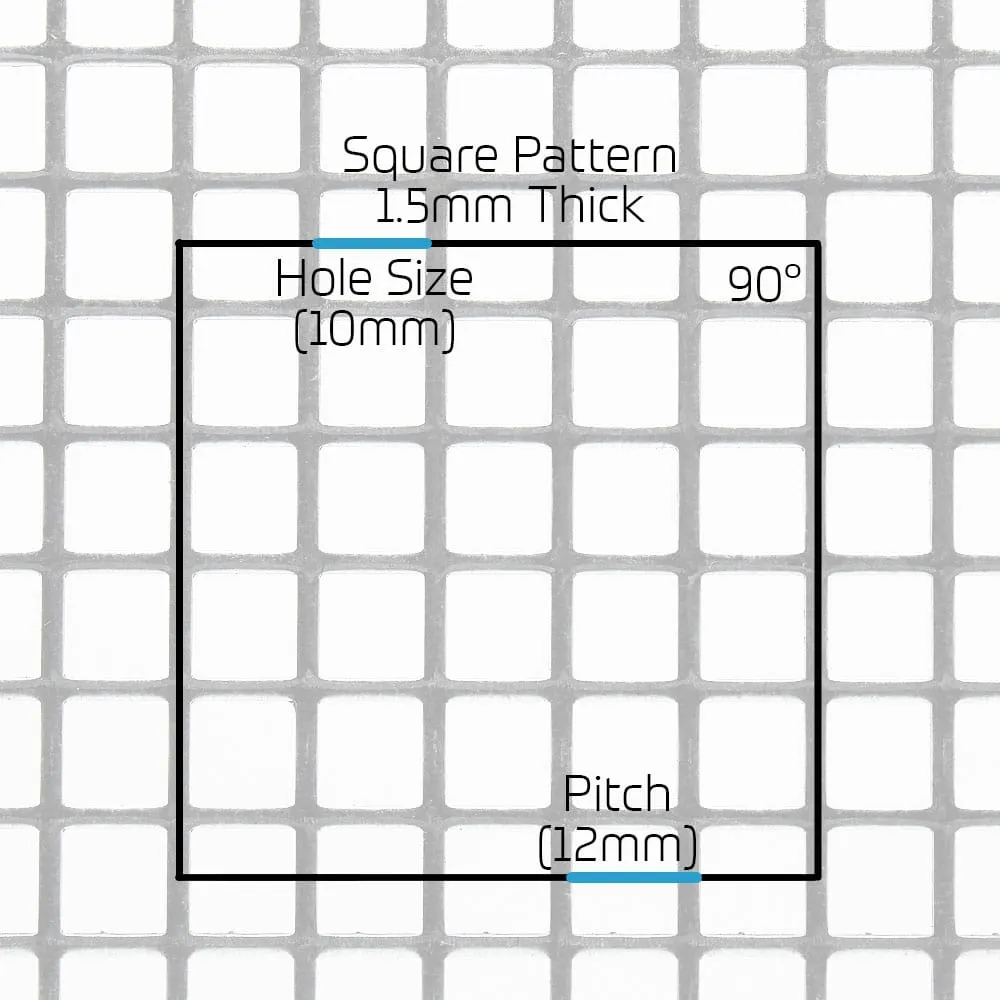
Ventilation patterns make the problem worse. A dense array of 4 mm holes on 6 mm centres leaves only 2 mm of metal between openings. In production that residual web softens under the laser heat or punches out of plane, so the finished panel no longer sits flat on the press-brake die. We see the same behaviour on slots: aspect ratios longer than 10:1 tend to close up slightly after cutting because the material on either side of the slot is free to move.
What shows up on the floor when the guidelines are ignored
Ignore the edge-distance rule and the first symptom is a panel that will not locate correctly in the bending fixture. The cutout edge has already moved 0.3–0.5 mm from residual stress, so the subsequent bend angle is off and the enclosure no longer meets the drawing. On ventilation arrays the thin webs buckle; the finished part looks wavy under fluorescent light and fails the flatness check. Assembly then has trouble with screw holes that no longer line up with the PCB mounting posts or the EMI gasket lands.
Slots that are too narrow relative to thickness leave burrs that the tumbling process cannot remove completely. Those burrs later catch on internal cabling or create intermittent ground paths that show up as EMI failures at the customer’s EMC lab. In high-volume runs we also see increased scrap when the laser has to slow down or the punch tool has to be cleaned more frequently because the small openings clog with dross. Shipment dates slip while the second-shift team reworks or re-cuts panels.
How the shop actually keeps cutouts inside tolerance
CAM engineers first run an automated check against the material thickness stored in the ERP. Any round hole smaller than 1× thickness is flagged; we either enlarge it to the minimum or move the feature to a secondary water-jet operation if the designer insists on the original size. Rectangular openings automatically receive a 0.5 mm minimum radius on every corner—larger if the thickness exceeds 2 mm—because the laser path cannot stop and reverse without leaving a divot. Slot widths are forced to at least the material thickness; lengths longer than 8–10× width get intermediate bridges left in the nest and removed after forming so the slot does not close.
Edge distance is protected by a keep-out zone in the nesting software: 1.5× thickness from any outer edge or from another cutout. When the designer has already packed the openings tighter, we shift the entire array inward by the required amount and note the change on the DFM report. For ventilation holes intended to preserve EMI shielding we keep the longest linear dimension of any opening below λ/20 of the highest frequency of interest (typically 5–8 mm for 1–2 GHz work). That limit is applied in the same CAM pass that checks mechanical rules, so the part does not leave the programming station with conflicting requirements.
Process parameters are locked once the cutout set is approved. Laser power and speed are reduced on dense arrays so the heat input stays low enough that the thin webs do not distort. Punch tooling is selected with the correct clearance and the stripper pressure is raised to hold the sheet flat. After cutting, panels go through a light deburr and a flatness check on a surface plate before they are released to forming. Any panel that exceeds 0.3 mm per 100 mm is either reworked or scrapped at that point rather than after bending.
When the factory will relax the numbers
We allow tighter edge distances only on soft aluminium under 1 mm thick when the part will not see any subsequent forming and the customer accepts a possible 0.2 mm local bow. Small round holes below 1× thickness are sometimes accepted if they are drilled as a secondary operation after the main laser or punch cycle, but the cost and lead-time increase are quoted up front. Dense ventilation patterns that violate the web rule can still run if the panel is left in a rigid nest frame until after all bending is complete and the bridges are removed last. EMI-critical openings are never relaxed; the λ/20 limit stays hard because the customer’s EMC test will catch any larger aperture. In every exception the trade-off—extra cost, extra process step, or relaxed flatness—is written into the order acknowledgment so both sides know what is being accepted.